


Maintenance
HON 512 with HON 650 pilot user manual
74
Figure
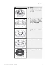
Step
Description
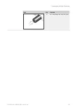
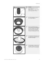
4
Take the inlet body. Remove the dia-
phragm unit.
5
Remove the compression spring.
6
Replace the O-ring (1) with a new, greased
O-ring. Follow the instructions in step 2.
7
Check the guide ring (2) for damage.
Replace it if necessary. Fill the chamber
with grease for valve sleeves (as per the
lubricant table) via the guide ring.
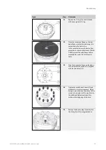
8
Check the compression spring for damage.
Replace it if necessary.
Place the compression spring back in the
inlet body.
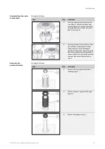
9
Take the diaphragm unit. Use the sleeve (3)
as a reference. The figure on the left shows
the sealing edge (1) facing upwards. This
sealing edge features a longer chamfer (2)
than the sleeve’s lower edge (4).
Summary of Contents for HON 512
Page 185: ...Appendix HON 512 with HON 650 pilot user manual 185 X Fail to open version Y Amplifying valve ...
Page 205: ...Appendix HON 512 with HON 650 pilot user manual 205 ...
Page 206: ...Appendix HON 512 with HON 650 pilot user manual 206 ...
Page 207: ...Appendix HON 512 with HON 650 pilot user manual 207 ...


