


Maintenance
HON 512 with HON 650 pilot user manual
110
Figure
Step
Description
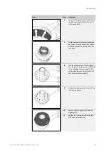
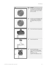
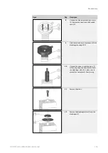
18
Lightly coat the thread surfaces with
threadlocker.
Put the cap in place.
Tighten the cap while using an open-end
wrench to hold the diaphragm plate in
place so as to prevent the components
from turning.
Observe the tightening torque information
provided in the table before this section.
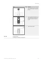
19
Remove the assembly aid (2) from the
valve body.
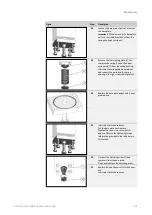
Screw the assembly aid (2) into the new
valve insert (1).
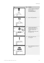
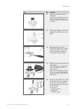
20
Position the valve body (1) as shown.
Turn the valve insert (2) in such a way that
the dowel pin will engage the intended
hole on the valve body (1) and the nozzle
opening is pointing upwards.
Insert the valve insert (2) as far as it will go
into the connecting piece (1).
21
Remove the assembly aid.
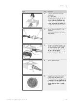
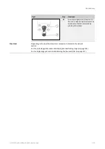
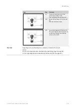
22
To align the cross hole of the connecting
piece correctly with the valve insert:
Use the cap to turn the diaphragm by hand
clockwise until it will not rotate any further.
Use a marker or pen to mark the position
on the body and on the convoluted dia-
phragm.
Summary of Contents for HON 512
Page 185: ...Appendix HON 512 with HON 650 pilot user manual 185 X Fail to open version Y Amplifying valve ...
Page 205: ...Appendix HON 512 with HON 650 pilot user manual 205 ...
Page 206: ...Appendix HON 512 with HON 650 pilot user manual 206 ...
Page 207: ...Appendix HON 512 with HON 650 pilot user manual 207 ...


