


Maintenance
HON 512 with HON 650 pilot user manual
73
Figure
Step
Description
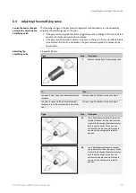
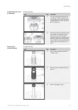
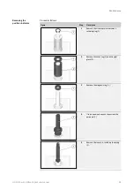
4
Use an open-end wrench to unscrew the
guide pin (1).
5
Remove the inner pin, including the spring
(1).
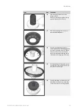
Proceed as follows:
Figure
Step
Description
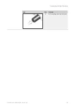
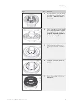
1
Unscrew the connection flange’s screws (1)
in a criss-cross sequence.
Please note that the spring will be exerting
a slight amount of pressure on the body.
Slowly unscrew the screws until the
compression spring’s pressure is relieved.
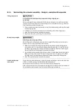
2
Turn the connection flange 180°. Remove
the two support rings (1). Replace the
O-ring (2) with a new, greased O-ring.
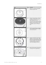
Insert the support rings back in place as
shown in the diagram on the top left. In
the case of nominal sizes DN > 50, the
support rings will not be split in a helical
pattern.
3
Check the guide ring (3) for damage.
Replace it if necessary. Fill the chamber
with grease for valve sleeves (as per the
lubricant table) via the guide ring.
Maintaining the inlet
body
Summary of Contents for HON 512
Page 185: ...Appendix HON 512 with HON 650 pilot user manual 185 X Fail to open version Y Amplifying valve ...
Page 205: ...Appendix HON 512 with HON 650 pilot user manual 205 ...
Page 206: ...Appendix HON 512 with HON 650 pilot user manual 206 ...
Page 207: ...Appendix HON 512 with HON 650 pilot user manual 207 ...


