


Transport, installation and start-up
HON 512 with HON 650 pilot user manual
47
Figure
Step
Description
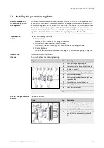
3
Remove the flange caps (1, 2).
4
Transport the device to the location where
it will be installed.
▪
The device needs to be installed in the
gas regulating line in a horizontal and
level position. If you want to use a dif-
ferent installation position, consult with
the manufacturer first.
▪
Pay attention to the direction of flow for
the gaseous fluid as marked on the
body.
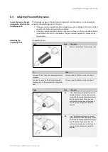
5
Secure and support the position of the
components you are installing in such a
way that the components can be installed
in the gas regulating line without any stress
and that the gas regulating line’s weight
will be supported as well.
6
Install the flange gaskets.
7
Insert the screws.
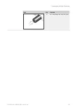
8
Tighten the screws on the flanges in a
criss-cross sequence. When doing so, make
sure to observe the torques specified by
the flange gaskets’ manufacturer.
Conduct a final inspection to check whether the following criteria are met:
All screws on the device have been checked to make sure that they have a secure fit.
If …
then …
at least one criterion is not met
you should correct the error before proceeding
with the next task.
all criteria are met
you may proceed with the next task.
Proceed as follows:
Installing the device connections
(see page 48)
Final inspection
Next task
Summary of Contents for HON 512
Page 185: ...Appendix HON 512 with HON 650 pilot user manual 185 X Fail to open version Y Amplifying valve ...
Page 205: ...Appendix HON 512 with HON 650 pilot user manual 205 ...
Page 206: ...Appendix HON 512 with HON 650 pilot user manual 206 ...
Page 207: ...Appendix HON 512 with HON 650 pilot user manual 207 ...


