


Appendix
HON 512 with HON 650 pilot user manual
171
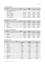
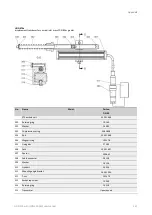
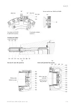
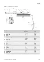
Spare parts list for HON 512 actuator assembly, design
3, DN 25
–
DN 100:
No.
Name
Maint.
DN
25
Part no.
DN
50
DN
80*
DN
100
6
Compression spring
7 X 65 X 58
10013287
-
-
-
10 x 97 x 85
-
10013387
-
-
16 x 168 x 130
-
-
-
10013637
7
Diaphragm disc
10013484
10013534
-
10013634
8
Diaphragms
ROLLING DIAPHRAGM 140/130-55 FTGT.
x
10013485
-
-
-
ROLLING DIAPHRAGM 200/190-60
x
-
10013535
-
-
ROLLING DIAPHRAGM 348/333-60 FTGT.
x
-
-
-
10013635
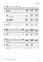
9
Mounting plate
10013486
18353705
-
10013636
10
Case for visual position indicator
10013280
10013380
10013380
10013639
11
Indicator pin for visual position indicator
10013491
10013541
10013541
10013641
12
Sight glass for visual position indicator
10013283
10013383
10013642
10013642
13
Compression spring for visual position indicator
10013284
10013384
10013384
19081838
14
Valve scale for visual position indicator
10013285
10013385
10013385
10013644
15
LOCK RING
10013286
10013286
10013286
10013286
16
LABEL FOR FLANGED THREADED HOLE
10013294
10013294
10013294
10013294
24
EYE BOLT
M10
10487-RMK
-
-
-
M12
-
10021
-
10021
25
Socket cap screw
M12 X 35
10563-RMK
(8 units)
-
-
-
M16 X 50
-
10555-RMK
(8 units)
-
-
M16 X 55
-
-
-
10609-RMK
(12 units)
27
M8 X 25 SOCKET CAP SCREW
-
10324
-
-
Summary of Contents for HON 512
Page 185: ...Appendix HON 512 with HON 650 pilot user manual 185 X Fail to open version Y Amplifying valve ...
Page 205: ...Appendix HON 512 with HON 650 pilot user manual 205 ...
Page 206: ...Appendix HON 512 with HON 650 pilot user manual 206 ...
Page 207: ...Appendix HON 512 with HON 650 pilot user manual 207 ...


