


Maintenance
HON 512 with HON 650 pilot user manual
100
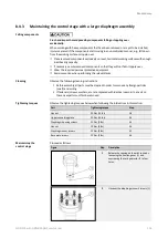
Proceed as follows:
Figure
Step
Description
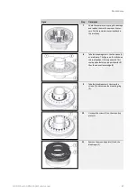
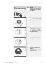
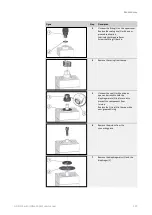
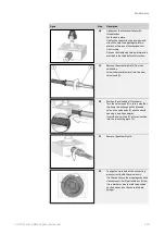
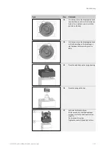
1
Replace the O-ring (1) in the body hole
intended for the position indicator with a
new, greased O-ring.
2
Insert the inner pin, including the spring
(1), back into the hole (2) for the position
indicator.
3
Use an open-end wrench to install the
guide pin (1) back in place.
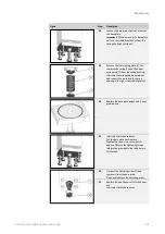
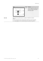
4
Place the magnetic ring (1) over the guide
pin. The magnetic ring position shown in
the figure to the left shows the correct
installation height.
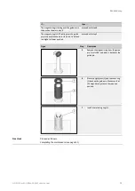
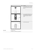
If …
then …
The magnetic ring is resting over the guide pin in
the position shown in step 4
proceed with step 6.
The magnetic ring is NOT resting over the guide
pin in the position shown in step 4, but is instead
in a higher or lower position
proceed with step 5.
Maintaining and in-
stalling the position
indicator
Summary of Contents for HON 512
Page 185: ...Appendix HON 512 with HON 650 pilot user manual 185 X Fail to open version Y Amplifying valve ...
Page 205: ...Appendix HON 512 with HON 650 pilot user manual 205 ...
Page 206: ...Appendix HON 512 with HON 650 pilot user manual 206 ...
Page 207: ...Appendix HON 512 with HON 650 pilot user manual 207 ...


