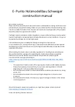
10
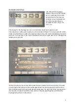
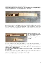
A straight line is drawn on the building board, extending along the entire length of the hull.
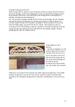
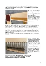
The fuselage tube is inserted into the fuselage boat so far that it protrudes 2mm from frame
R4.
The frame R5 is inserted into the rear of the fuselage boat. 1cm before the end of the fuselage
boom the support made of 3mm balsa is inserted.
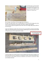
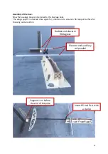
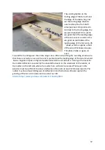
On the rear surface screw connection, a straight strip with a length of approx. 40cm, in an
angle of 90 degrees to the fuselage center line is screwed on (this serves us as an assistance
for the alignment).
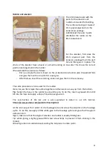
Now all parts can be aligned, parallel to the drawn line. The fuselage tube lies neatly in the
holder, the fuselage lies flat in the fuselage slipway.
The elevator lies parallel to our screwed-on auxiliary rail. The fuselage side panels are pressed
to frame R5 with clamps. Before gluing, check again for correct alignment.
The fuselage must lie without tension in its slipway and end support.
Only a correctly aligned fuselage ensures optimum flight characteristics.
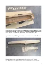
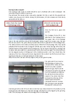
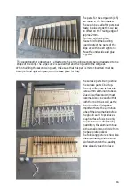
The final work on the hull now includes the transition from the hull boat to the hull tube,
which is done with the two parts R24. These are fitted to the end of the fuselage boat and
glued with the straight side facing upwards.
Fuselage tube
protrudes 2mm above
Straight side points
upwards

