


Rev. 2.10
178
���� 02� 201�
Rev. 2.10
179
���� 02� 201�
HT68F20/HT68F30/HT68F40/HT68F50/HT68F60
HT68FU30/HT68FU40/HT68FU50/HT68FU60
Enhanced I/O Flash Type 8-Bit MCU with EEPROM
HT68F20/HT68F30/HT68F40/HT68F50/HT68F60
HT68FU30/HT68FU40/HT68FU50/HT68FU60
Enhanced I/O Flash Type 8-Bit MCU with EEPROM
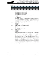
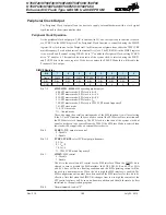
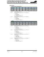
SIMC0 Register
Bit
7
6
5
4
3
2
1
0
Name
SIM2
SIM1
SIM0
PCKEN
PCKP1
PCKP0
SIMEN
—
R/W
R/W
R/W
R/W
R/W
R/W
R/W
R/W
—
POR
1
1
1
0
0
0
0
—
Bit 7~5
SIM2, SIM1, SIM0
: SIM Operating Mode Control
000: SPI master mode; SPI clock is f
SYS
/4
001: SPI master mode; SPI clock is f
SYS
/16
010: SPI master mode; SPI clock is f
SYS
/64
011: SPI master mode; SPI clock is f
TBC
100: SPI master mode; SPI clock is TM0 CCRP match frequency/2
101: SPI slave mode
110: I
2
C slave mode
111: Unused mode
These bits setup the overall operating mode of the SIM function. As well as selecting
if the I
2
C or SPI function, they are used to control the SPI Master/Slave selection and
the SPI Master clock frequency. The SPI clock is a function of the system clock but
can also be chosen to be sourced from the TM0. If the SPI Slave Mode is selected then
the clock will be supplied by an external Master device.
Bit 4
PCKEN
: PCK Output Pin Control
0: Disable
1: Enable
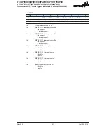
Bit 3~2
PCKP1, PCKP0
: Select PCK output pin frequency
00: f
SYS
01: f
SYS
/4
10: f
SYS
/8
11: TM0 CCRP match frequency/2
Bit 1
SIMEN
: SIM Control
0: Disable
1: Enable
The bit is the overall on/off control for the SIM interface. When the SIMEN bit is
cleared to zero to disable the SIM interface, the SDI, SDO, SCK and SCS, or SDA
and SCL lines will be in a floating condition and the SIM operating current will be
reduced to a minimum value. When the bit is high the SIM interface is enabled. The
SIM configuration option must have first enabled the SIM interface for this bit to be
effective. If the SIM is configured to operate as an SPI interface via SIM2~SIM0 bits,
the contents of the SPI control registers will remain at the previous settings when the
SIMEN bit changes from low to high and should therefore be first initialised by the
application program. If the SIM is configured to operate as an I
2
C interface via the
SIM2~SIM0 bits and the SIMEN bit changes from low to high, the contents of the I
2
C
control bits such as HTX and TXAK will remain at the previous settings and should
therefore be first initialised by the application program while the relevant I
2
C flags
such as HCF, HAAS, HBB, SRW and RXAK will be set to their default states.
B
it 0
Unimplemented, read as “0”


