


Rev. 2.10
13�
���� 02� 201�
Rev. 2.10
135
���� 02� 201�
HT68F20/HT68F30/HT68F40/HT68F50/HT68F60
HT68FU30/HT68FU40/HT68FU50/HT68FU60
Enhanced I/O Flash Type 8-Bit MCU with EEPROM
HT68F20/HT68F30/HT68F40/HT68F50/HT68F60
HT68FU30/HT68FU40/HT68FU50/HT68FU60
Enhanced I/O Flash Type 8-Bit MCU with EEPROM
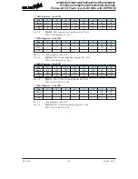
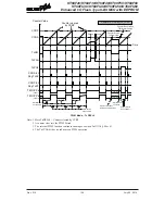
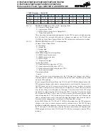
10-bit STM, PWM Mode, Edge-aligned Mode, TnDPX=0
CCRP
001b
010b
011b
100b
101b
110b
111b
000b
Period
128
256
38�
512
6�0
768
896
102�
D�t�
CCRA
If f
SYS
=16MHz, TM clock source is f
SYS
/4, CCRP=100b and CCRA=128,
The STM PWM output frequency=(f
SYS
/4)/512=f
SYS
/2048=7.8125kHz, duty=128/512=25%.
If the Duty value defined by the CCRAregister is equal to or greater than the Period value, then the
PWM output duty is 100%.
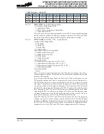
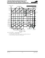
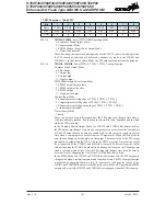
10-bit STM, PWM Mode, Edge-aligned Mode, TnDPX=1
CCRP
001b
010b
011b
100b
101b
110b
111b
000b
Period
CCRA
D�t�
128
256
38�
512
6�0
768
896
102�
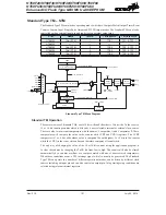
The PWM output period is determined by the CCRAregister value together with the TM clock while
the PWM duty cycle is defined by the CCRP register value.
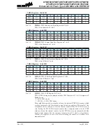
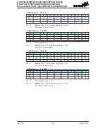
16-bit STM, PWM Mode, Edge-aligned Mode, TnDPX=0
CCRP
1~255
0
Period
CCRP×256
65536
D�t�
CCRA
If f
SYS
=16MHz, TM clock source is f
SYS
/4, CCRP=2 and CCRA=128,
The STM PWM output frequency=(f
SYS
/4)/(2×256)=f
SYS
/2048=7.8125kHz, duty=128/(2×256)=25%.
If the Duty value defined by the CCRAregister is equal to or greater than the Period value, then the
PWM output duty is 100%.
16-bit STM, PWM Mode, Edge-aligned Mode, TnDPX=1
CCRP
1~255
0
Period
CCRA
D�t�
CCRP×256
65536
The PWM output period is determined by the CCRAregister value together with the TM clock while
the PWM duty cycle is defined by the (CCRP×256) except when the CCRP value is equal to 0.


