


Rev. 2.10
126
���� 02� 201�
Rev. 2.10
127
���� 02� 201�
HT68F20/HT68F30/HT68F40/HT68F50/HT68F60
HT68FU30/HT68FU40/HT68FU50/HT68FU60
Enhanced I/O Flash Type 8-Bit MCU with EEPROM
HT68F20/HT68F30/HT68F40/HT68F50/HT68F60
HT68FU30/HT68FU40/HT68FU50/HT68FU60
Enhanced I/O Flash Type 8-Bit MCU with EEPROM
16-bit Standard TM Register List – HT68F40/HT68F50/HT68F60
•
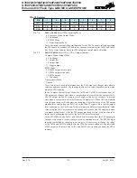
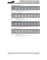
TM2C0 Register – 16-bit STM
Bit
7
6
5
4
3
2
1
0
Name
T2PAU
T2CK2
T2CK1
T2CK0
T2ON
—
—
—
R/W
R/W
R/W
R/W
R/W
R/W
—
—
—
POR
0
0
0
0
0
—
—
—
Bit 7
T2PAU
: TM2 Counter Pause Control
0: Run
1: Pause
The counter can be paused by setting this bit high. Clearing the bit to zero restores
normal counter operation. When in a Pause condition the TM will remain powered up
and continue to consume power. The counter will retain its residual value when this bit
changes from low to high and resume counting from this value when the bit changes
to a low value again.
Bit 6~4
T2CK2, T2CK1, T2CK0
: Select TM2 Counter clock
000: f
SYS
/4
001: f
SYS
010: f
H
/16
011: f
H
/64
100: f
TBC
101: Undefined
110: TCK2 rising edge clock
111: TCK2 falling edge clock
These three bits are used to select the clock source for the TM. Selecting the Reserved
clock input will effectively disable the internal counter. The external pin clock source
can be chosen to be active on the rising or falling edge. The clock source f
SYS
is the
system clock, while f
H
and f
TBC
are other internal clocks, the details of which can be
found in the oscillator section.
Bit 3
T2ON
: TM2 Counter On/Off Control
0: Off
1: On
This bit controls the overall on/off function of the TM. Setting the bit high enables the
counter to run, clearing the bit disables the TM. Clearing this bit to zero will stop the
counter from counting and turn off the TM which will reduce its power consumption.
When the bit changes state from low to high the internal counter value will be reset to
zero, however when the bit changes from high to low, the internal counter will retain
its residual value until the bit returns high again.
If the TM is in the Compare Match Output Mode then the TM output pin will be reset
to its initial condition, as specified by the T2OC bit, when the T2ON bit changes from
low to high.
Bit 2~0
Unimplemented, read as “0”


