[72]
□
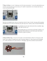
Step 12: Install C3 –
Insert it into the PCB, carefully observing the polarity, solder the leads and closely
trim the excess leads.
□
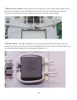
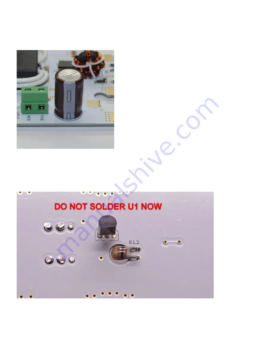
Step 13: Install U1 and R13 –
U1 and R13 are mounted on the back side of the PCB. Insert U1 aligning the
flat side of the component with the flat side indicated on the silkscreen. R13 is not polarized just insert the leads
into the holes and bend the component so the body is in the opening in the PCB.
Solder R13 and trim the excess leads. The AN-1918 is now ready to mount on a suitable heatsink.


