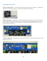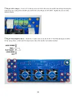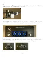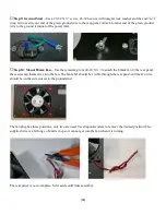
[40]
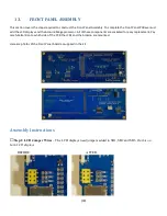
Use a component lead or small piece of wire to solder across the space between the pads of SB1, SB2 and SB3
as shown. For those not intimidated by SMT components, low value resistors will work fine and are easier (I
think) to deal with than the jumper wires. Any resistor less than 100 ohms will be sufficient.
Be very careful working with the LCDs the surface is glass and can crack if dropped or twisted. Always
handle the display by the edges and if you need to push it into the socket do not press on the glass, press
on the PCB edges.
□
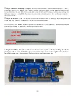
Step 2: Stacking Headers
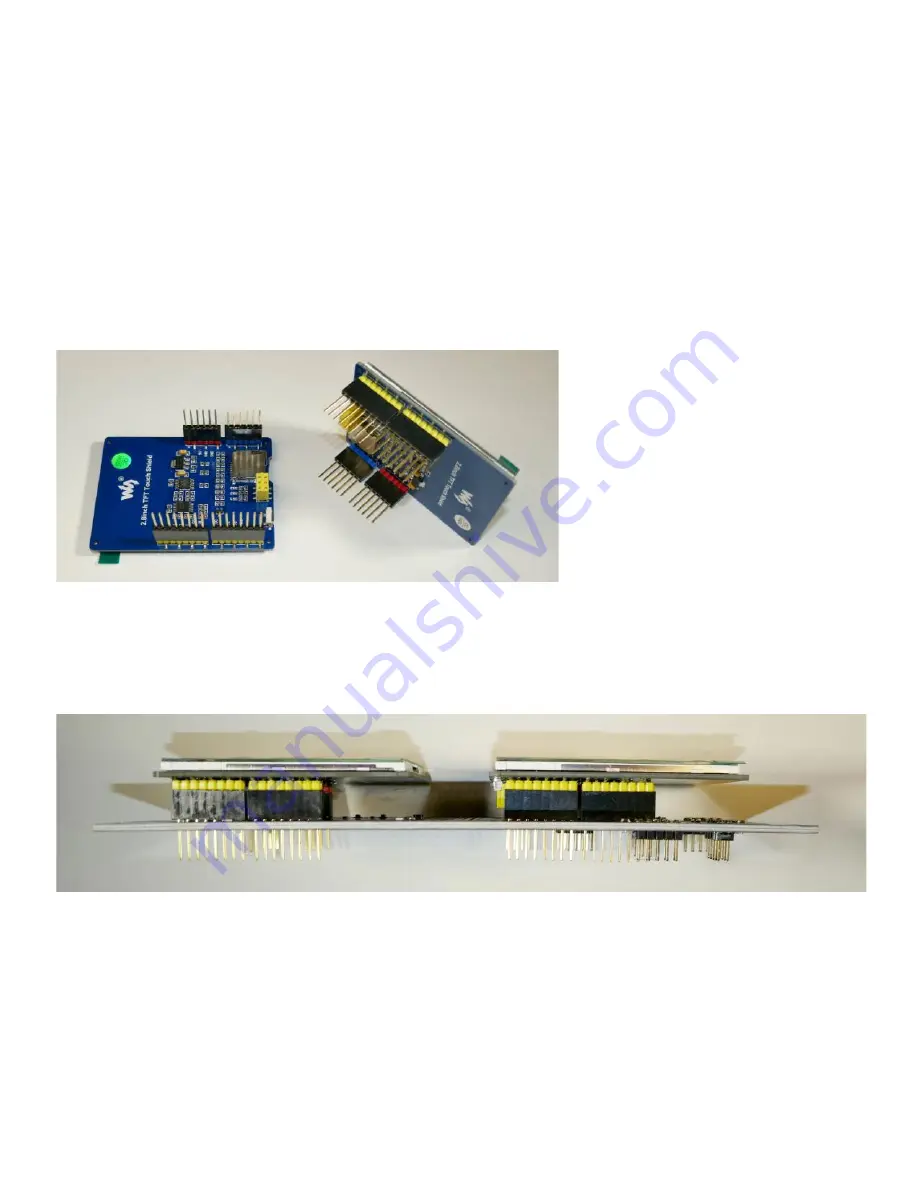
– Carefully slide the Arduino stacking headers onto the pins of the LCDs. There
are 6-pin and 8-pin headers, make sure that the placement is correct.
□
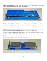
Step 3: Mount LCDs
– On the side of the front panel PCB that says “INSTALL LCD DISPLAYS ON THIS
SIDE”, insert the LCDs with the stacking headers attached. It’s a bit of a challenge to get all of the pins lined
up.
□
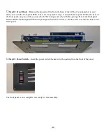
Step 4: Solder/Check LCDs
– Start by placing the assembly on a flat surface and soldering a single pin on
either side of each LCD then press down on the PCB close to the pin to ensure that the header is fully seated.
Then check the alignment. It is critical that the headers are fully seated, flush with the PCB and perpendicular to
the PCB.

