Chapter 2 Syntax
2.5 Timer
Control
Instructions
The easy sequence function of the inverter has a timer function that can be used in the following two modes:
(1) Free-running timer mode
(2) Timer contact output mode (timer-start, timer-stop, and delay operations)
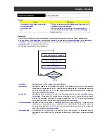
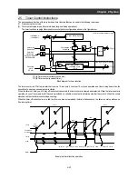
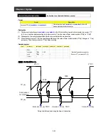
The timer function uses eight timer counter circuits that are configured as shown in the figure below.
㻢
Timer buffer (count)
Comparison for
matching
Latch
CLR
S
R
Q
Counting
cycle
(10 ms)
timer set
instruction
delay on/delay
off instruction
TD (k)
TC (k)
32
32
32
32
32
1
Up counter
(counting cycle:
10 ms)
CLR
UP
<variable> or
<constant>
timer stop
instruction
In free-running timer mode
In timer contact output mode
TC (k): Timer counter variable (up counter)
TD (k): Timer contact (one-shot timer)
Block diagram for timer function
The timer counter is a 31-bit up counter that runs in a 10-ms cycle (1 count per 10 ms), and operates as a free-running timer when the
execution of a easy sequence program is started.
When the timer set, delay on, or delay off instruction is executed, the timer counter is cleared and restarted. While the timer counter is
operating, its count is compared with the count specified by a variable or constant to determine whether they match. When the counts
match each other, the timer counter stops counting.
When the timer off instruction is executed, the timer counter is cleared and restarted. Subsequently, the timer counter operates as a
free-running timer.
delay on Y (00) TD (0) 1000
delay off Y (00) TD (0) 1500
TC (0)
TD (0)
timer off TD (0)
Comparison
for matching
1500
1000
Y (00)
2^31-1
[PRN]
The
counter
starts.
2^31-1
Example of timer function operation
2-23
Summary of Contents for NT2021XA
Page 4: ... Safety Instructions ...
Page 8: ... Contents ...
Page 10: ...Chapter 1 Outline of EzSQ ...
Page 14: ...1 4 Chapter 1 Outline of EzSQ ...
Page 16: ...Chapter 2 Syntax ...
Page 68: ...2 52 Chapter 2 Syntax ...
Page 70: ...Chapter 3 Interface with the Inverter ...
Page 80: ...3 10 Chapter 3 Interface with the Inverter ...

