Chapter 2 Syntax
2-18
2.4
Input/Output Control Instructions
This section describes the details of input/output control instructions.
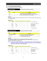
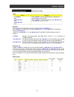
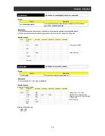
X ( ) or Xw (contact input)
Instruction to access contact inputs
- Format
Format
Description
1
<variable>
= X (ii)
(SJ700 : ii = 00 to 07)
(WJ200 : ii = 00 to 09)
This instruction assigns the ii'th bit of contact input data to
<variable>
.
2
<variable>
= Xw
This instruction assigns contact input data as word data to
<variable>
.
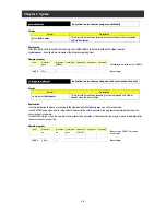
- Explanation
This instruction fetches the status of contact input terminals X (ii) and stores it in
<variable>
in units of bits or words. You cannot
write data to
<variable>
, which is read-only. Details of the formats are explained below.
Format 1 : With this format, the instruction assigns the status of the ii'th bit of contact input data to
<variable>
. (0 = off, 1 = on)
(Examples)
When terminal X (00) is off: UB= X (00) (UB (00) = 0)
When terminal X (00) is on: UB= X (01) (UB (00) = 1)
Format 2 : With this format, the instruction assigns the status of contact input data as word data to
<variable>
. (0 = off, 1 = on)
(Examples)
When terminals X (00) to X (03) are on and terminals X (04) to X (07) are off: Uw= Xw (Uw = 15)
When terminals X (00) to X (02) are off and terminals X (03) to X (07) are on: Uw= Xw (Uw = 248)
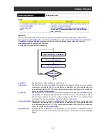
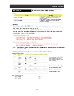
Note 1 : In the SJ700/L700/SJ700B Series, the setting of terminal active state (C011 to C018) is reflected in the
polarity (on or off) of contact inputs X (00) to X (07) and Xw. When you create a user program, consider the
on and off states of actual intelligent input terminals 1 to 8.
In the WJ200 Series, the setting of terminal active state (C011 to C017) is reflected in the polarity (on or off)
of contact inputs X (00) to X (06) and Xw. When you create a user program, consider the on and off states of
actual intelligent input terminals 1 to 7.
Note 2 : Since this instruction reads the internal input terminal data at least twice (in two execution cycles), storing
the read data in <variable> is delayed by at least two execution cycles.
Note 3 : Wiring noise or switch chattering may cause incorrect read data to be set in <variable>. To avoid such
problems, design your program so that it will verify the read data.
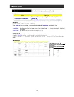
- Sample program
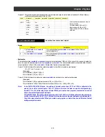
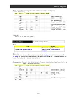
Sample 1 : Program to invert the status data of input terminal X (01) and output it to output terminal Y (05)
Label
Mnemonic
parameter1
parameter2
parameter3
parameter4
parameter5
㩷
㩷
entry
㩷
㩷
㩷
㩷
㩷
㩷
LOOP UB(00)=
㩷
㩷
X(01)
㩷
㩷
: Fetch the status of X (01) and store it as
internal user contact data.
㩷
ifs UB(00)
=
0
㩷
㩷
: Branch according to the conditional
expression.
㩷
then
㩷
㩷
㩷
㩷
㩷
㩷
Y(05)= 1
㩷
㩷
㩷
㩷
: Turn Y (05) on when the condition is met.
㩷
else
㩷
㩷
㩷
㩷
㩷
㩷
Y(05)= 0
㩷
㩷
㩷
㩷
: Turn Y (05) off when the condition is not
met.
㩷
end if
㩷
㩷
㩷
㩷
㩷
㩷
㩷
goto LOOP
㩷
㩷
㩷
㩷
㩷
㩷
end
㩷
㩷
㩷
㩷
㩷
㩷
Summary of Contents for NT2021XA
Page 4: ... Safety Instructions ...
Page 8: ... Contents ...
Page 10: ...Chapter 1 Outline of EzSQ ...
Page 14: ...1 4 Chapter 1 Outline of EzSQ ...
Page 16: ...Chapter 2 Syntax ...
Page 68: ...2 52 Chapter 2 Syntax ...
Page 70: ...Chapter 3 Interface with the Inverter ...
Page 80: ...3 10 Chapter 3 Interface with the Inverter ...


