Chapter 2 Syntax
2-19
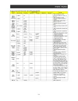
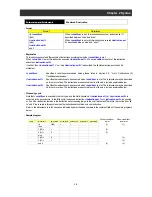
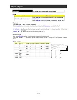
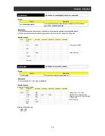
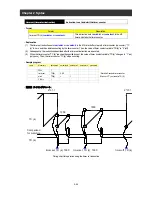
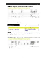
Sample 2 : Program to acquire input terminal status as word data and output only the status of terminals X (02) to X (05) as
word data to output terminals Y (00) to Y (03)
Label
Mnemonic
parameter1
parameter2
parameter3
parameter4
parameter5
㩷
㩷
entry
㩷
㩷
㩷
㩷
㩷
㩷
LOOP U(00)=
Xw
㩷
㩷
㩷
: Fetch input terminal status and store it in
the user variable.
㩷
U(00)= U(00)
/
4
㩷
㩷
: Cut off the data of X (00) to X (01).
㩷
U(00)= U(00)
and 15
㩷
㩷
: Mask the data of X (06) to X (07).
㩷
Yw= U(00)
㩷
㩷
㩷
: Output the data of X (02) to X (05) as
word data.
㩷
goto LOOP
㩷
㩷
㩷
㩷
㩷
end
㩷
㩷
㩷
㩷
㩷
㩷
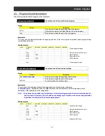
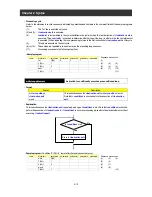
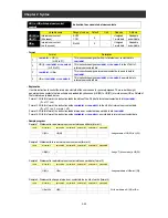
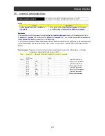
Y ( ) or Yw (contact output)
Instruction to access contact outputs
- Format
Format
Description
1
Y (ii)=
<variable>
or
<constant>
(ii = 00 to 05)
This instruction assigns
<variable>
or
<constant>
to the ii'th bit of
contact output data.
2
Yw=
<variable>
or
<constant>
This instruction assigns
<variable>
or
<constant>
as word data to
contact outputs.
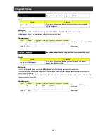
- Explanation
This instruction writes
<variable>
or
<contact>
to contact output terminals Y (00) to X (05) in units of bits or words to output the
data. You can write and read data to and from
<variable>
or
<contact>
. You can also fetch and store the status data of contact
output terminals Y (00) to Y (05) in
<variable>
. Details of the formats are explained below.
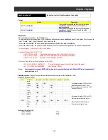
Format 1 : With this format, the instruction outputs
<variable>
to the ii'th bit of contact output terminal.
(0 = off, 1 = on, 2 or more = off)
(Examples)
To turn terminal Y (00) off: Y (00)= 0
To turn terminal Y (01) on: Y (01)= 1
Format 2 : With this format, the instruction outputs
<variable>
as word data to contact output terminals.
(Examples)
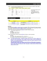
To turn terminal Y (00) on and turn terminals Y (01) to Y (05) off: Yw= 1
To turn terminals Y (00) to Y (04) off and turn terminal Y (05) on: Yw= U (00) (U (00) = 32)
Note : In the SJ700/L700/SJ700B Series, the setting of terminal active state (C031 to C036) is reflected in the
polarity (on or off) of contact inputs Y (00) to Y (05) and Yw when the data is output to intelligent output
terminals 11 to 15 and the relay output terminal. When you create a user program, consider the on and off
states of actual intelligent output terminals.
In the WJ200 Series, the setting of terminal active state (C031, C032, and C036) is reflected in the polarity (on
or off) of contact inputs Y (00), Y (01), Y (05) and Yw when the data is output to intelligent output terminals 11,
12 and the relay output terminal. When you create a user program, consider the on and off states of actual
intelligent output terminals.
Summary of Contents for NT2021XA
Page 4: ... Safety Instructions ...
Page 8: ... Contents ...
Page 10: ...Chapter 1 Outline of EzSQ ...
Page 14: ...1 4 Chapter 1 Outline of EzSQ ...
Page 16: ...Chapter 2 Syntax ...
Page 68: ...2 52 Chapter 2 Syntax ...
Page 70: ...Chapter 3 Interface with the Inverter ...
Page 80: ...3 10 Chapter 3 Interface with the Inverter ...

