

KH-WS1
– 3 –
SERVICE POINTS
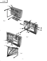
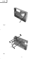
1. Removal of Back Case (Fig. 1)
(1) Remove 3 screws
1
from the back and 2 screws
2
inside the battery compartment.
(2) Detach the Antenna from the Ant
}
.
(3) Detach the connector
A
.
2. Removal of SATELLITE P.W.B. Board (Fig. 2)
(1) Detach all connectors
B
,
C
and
D
.
(2) Remove 1 screw
3
from the Satellite P.W.B. Board.
(3) Remove 2 screws
4
from the Satellite P.W.B. Board.
(4) Release the 3 catches and slide the Satellite P.W.B. Board away.
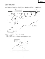
2. Removal of TUNER P.W.B. Board (Fig. 3)
(1) Detach 5 connectors
E
,
F
,
G
,
H
and
I
from the Tuner P.W.B. Board.
(2) Turn to the opposite side, remove 1 screw
5
from the Tuner P.W.B. Board.
(3) Detach 9 catches and separate the Tuner P.W.B. Board from the sub-chassis.
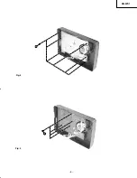
3. Removal of Insulator Pad (Fig. 4)
(1) Remove 6 screws
5
from the Insulator pad.
4. Removal of Main Board (Fig. 5)
(1) Remove 4 screws
6
from the Main Board.
5. Removal of Speaker (Fig. 6)
(1) Release one end of the metal pin that secures the speaker position.
(2) Slide out the speaker.
6. Removal of POWER SUPPLY P.W.B. Board (Fig. 7)
(1) Remove 4 screws
7
and detach 1 connector
J
from the Power Supply P.W.B. board.
7. Removal of ANTENNA P.W.B. Board (Fig. 7)
(1) Remove 1 screw
9
from the Antenna P.W.B. board.
(2) Gently pull the Antenna P.W.B. board outwards.
8. Removal of WS ANTENNA SUPPORT PLATE (Fig. 7)
(1) Remove the 6 screws
8
and pull the WS Antenna Support Plate away from the Back case.
KH/Pg 03 (Service Pt)
10/11/00, 2:23 PM
3
Summary of Contents for KHWS1W
Page 5: ...KH WS1 5 Fig 4 Fig 5 5 6 ...
Page 6: ...KH WS1 6 Fig 6 Fig 7 metal pin 7 8 Connector J 9 ...
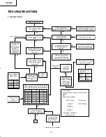
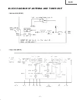
Page 17: ...KH WS1 17 BLOCK DIAGRAM OF ANTENNA AND TUNER UNIT Antenna Unit RF001 Tuner Unit RF101 ...
Page 26: ...KH WS1 26 TA7368P IC206 207 BU4066BCF IC204 BA033ST V5 IC209 1 9 7 8 1 14 1 2 3 4 5 ...
Page 28: ...KH WS1 28 TC9298F IC302 ...
Page 32: ...KH WS1 32 SATELLITE P W B TUNER PWB Soldering Side Soldering Side ...
Page 33: ...KH WS1 33 Component Side TUNER PWB SATELLITE P W B Component Side ...
Page 34: ...KH WS1 34 Soldering Side MAIN PWB ...
Page 35: ...KH WS1 35 MAIN P W B Component Side ...
Page 37: ...KH WS1 CIRCUIT DIAGRAM TUNER DTS Circuit 38 37 it A2 10 11 00 1 57 PM 37 ...
Page 38: ...CIRCUIT DIAGRAM ATELLITE Circuit 40 39 it A2 10 11 00 1 57 PM 38 ...
Page 39: ...KH WS1 42 41 BLOCK DIAGRAM Lk Xploded A3 10 11 00 2 00 PM 41 ...
Page 41: ...THE UPDATED PARTS LIST FOR THIS MODEL IS AVAILABLE ON ESTA ...


