
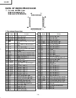
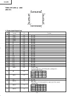

KH-WS1
– 15 –
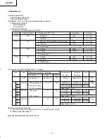
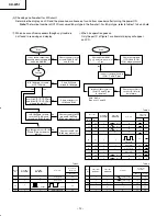
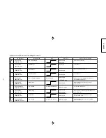
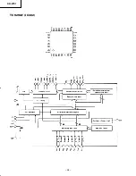
3. Check IC 24LC194 (IC107, E
2
PROM) of WS function
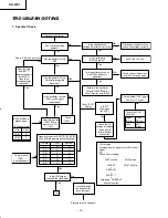
Check the following after turning the
power ON with displays on LCD or key operations.
Will the LCD display change
as follows?
When there is no signal
WS SAT
AFRST – 1 or
AFRST – 1
"SEARCH"
NO BEAM
OK
(Frashing)
e g)
*
Does the display followed
"WS SAT" on LCD become
one of next cases?
Case 1
Case 2
Case 3
The next display is
not appeared on
LCD.
The next operation
does not go on with
"SEARCH" blinks.
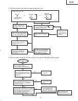
Push MODE Key
Turn on light "MODE"
Push PASSWORD Key
Push PASSWORD Key
Push PASSWORD Key
"ID"
"PASSW – 02"
"PASSW – 01"
Check IC107, it may
be in failure.
When it can
not operate
Description of LCD display
Press it successively.
Press it secondly.
Press it thirdly.
The ID number is displayed on
LCD after 2 seconds.
If "1234"
LCD display
LCD display
Press SC Up key.
Second half ID
"00001234"
First half ID
number always
"00000000"
OK
KH/Pg 10-17 (TroubleSht)
10/11/00, 1:50 PM
15
Summary of Contents for KHWS1W
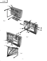
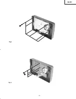
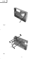
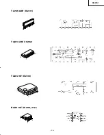
Page 5: ...KH WS1 5 Fig 4 Fig 5 5 6 ...
Page 6: ...KH WS1 6 Fig 6 Fig 7 metal pin 7 8 Connector J 9 ...
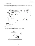
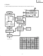
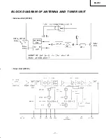
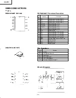
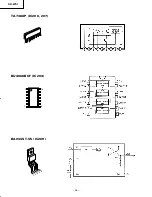
Page 17: ...KH WS1 17 BLOCK DIAGRAM OF ANTENNA AND TUNER UNIT Antenna Unit RF001 Tuner Unit RF101 ...
Page 26: ...KH WS1 26 TA7368P IC206 207 BU4066BCF IC204 BA033ST V5 IC209 1 9 7 8 1 14 1 2 3 4 5 ...
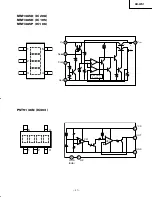
Page 28: ...KH WS1 28 TC9298F IC302 ...
Page 32: ...KH WS1 32 SATELLITE P W B TUNER PWB Soldering Side Soldering Side ...
Page 33: ...KH WS1 33 Component Side TUNER PWB SATELLITE P W B Component Side ...
Page 34: ...KH WS1 34 Soldering Side MAIN PWB ...
Page 35: ...KH WS1 35 MAIN P W B Component Side ...
Page 37: ...KH WS1 CIRCUIT DIAGRAM TUNER DTS Circuit 38 37 it A2 10 11 00 1 57 PM 37 ...
Page 38: ...CIRCUIT DIAGRAM ATELLITE Circuit 40 39 it A2 10 11 00 1 57 PM 38 ...
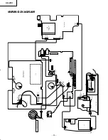
Page 39: ...KH WS1 42 41 BLOCK DIAGRAM Lk Xploded A3 10 11 00 2 00 PM 41 ...
Page 41: ...THE UPDATED PARTS LIST FOR THIS MODEL IS AVAILABLE ON ESTA ...


