
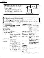
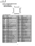

KH-WS1
– 9 –
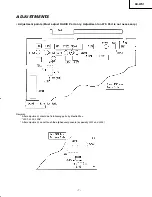
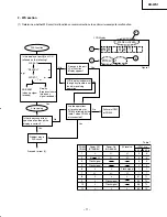
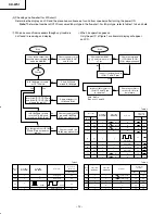
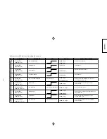
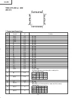
(4) Alignment for FM IF and FM Tracking
Note:
1. Feed in a week signal from the Genescope.
Adjust T202 for max. gain and the waveform
of Fig. 1.
2. Connect AM signal generator to loop antenna,
bring near to ferrite antenna.
3. Input signal methode as follows.
4. Feed in a week signal to IC201 (Note 3) from the
genescope. Use the T201 core to from the S-
curve shown in the Fig. 2.
Adjust the symmetry of A and B about point C for
linearity.
5. SW1, SW2 dummy antenna is shown in Fig. 3.
6. FM dummy antenna is shown in Fig. 4.
R1=Rg=SG's output impedance (75
Ω
),
R2=75 - Rg/2
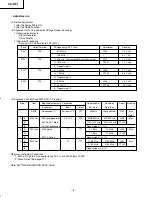
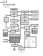
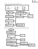
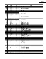
(5) Alignment for Clock Time Accuracy
Step
Item
1
IF
2
(1)
FM
(2)
(3)
Required Instrument & Connection
Instrument
Input
Output
Genescope
IC201
TP1
Note 3
FM signal
P1
TP1
Generator
400 Hz, 22.5 kHz Dev
Note 6
Genescope or
Receiving
Adjust
Reading
SG Freq.
Freq. (Set)
10.7 MHz
High End (or
T201
Max.
106.1 MHz)Freq.
Note 4
90.2 MHz
90.2 MHz
L201
Max.
106.1 MHz
106.1 MHz
CT201
Repeat steps (1) & (2)
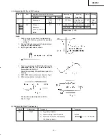
Band
Adjustment
FM
CT301
Procedure
Connection
1) Tune FM to 108 MHz
2) Connect a Freq. Counter to J308
To J308
3) Adjust CT301 to reach the frequency
To Counter
118.7 MHz ±1.5 kHz
KH/Pg 07-09 (Adjustment)
10/11/00, 1:48 PM
9
Summary of Contents for KHWS1W
Page 5: ...KH WS1 5 Fig 4 Fig 5 5 6 ...
Page 6: ...KH WS1 6 Fig 6 Fig 7 metal pin 7 8 Connector J 9 ...
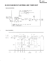
Page 17: ...KH WS1 17 BLOCK DIAGRAM OF ANTENNA AND TUNER UNIT Antenna Unit RF001 Tuner Unit RF101 ...
Page 26: ...KH WS1 26 TA7368P IC206 207 BU4066BCF IC204 BA033ST V5 IC209 1 9 7 8 1 14 1 2 3 4 5 ...
Page 28: ...KH WS1 28 TC9298F IC302 ...
Page 32: ...KH WS1 32 SATELLITE P W B TUNER PWB Soldering Side Soldering Side ...
Page 33: ...KH WS1 33 Component Side TUNER PWB SATELLITE P W B Component Side ...
Page 34: ...KH WS1 34 Soldering Side MAIN PWB ...
Page 35: ...KH WS1 35 MAIN P W B Component Side ...
Page 37: ...KH WS1 CIRCUIT DIAGRAM TUNER DTS Circuit 38 37 it A2 10 11 00 1 57 PM 37 ...
Page 38: ...CIRCUIT DIAGRAM ATELLITE Circuit 40 39 it A2 10 11 00 1 57 PM 38 ...
Page 39: ...KH WS1 42 41 BLOCK DIAGRAM Lk Xploded A3 10 11 00 2 00 PM 41 ...
Page 41: ...THE UPDATED PARTS LIST FOR THIS MODEL IS AVAILABLE ON ESTA ...


