
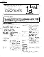
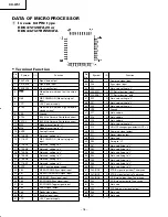
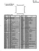
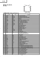
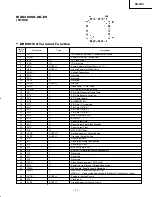

KH-WS1
– 10 –
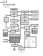
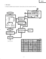
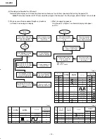
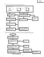
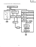
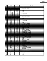
TROUBLESHOOTING
No
No
No
No
No
Yes
Yes
Yes
Yes
Yes
Yes
Yes
No
Yes
No
No
Yes
Yes
No
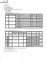
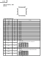
V in
Pin No.
21
22
23
50
51
53
WS
H
H
L
H
H
H
RADIO
H
L
H
L
H
H
>3.6V
<3.6V
V out
H
L
No
No
Yes
Yes
OK
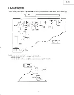
Connect to AC outlet.
Can the time display
appear?
Can the power SW turn
ON?
Can the power SW turn
ON after pressing the
Reset key?
Is the oscillator circuit of
IC301 and pin
in operation?
Check IC301 control circuit.
Does the time
and "BATT"
displays appear
on the LCD,
then they
disappear after
2 seconds?
Check
IC301.
Does the port of
IC301 pin
operate in "H"?
(+3V)
IC303 or Q303 is
broken down.
IC303 operation
Does every port of IC301 ,
,
,
,
and
pin operate on the following?
Check around
IC301.
Is it broken down?
Is the LCD display
followed the right table?
Check and follow
the flowchart for
each functions.
Proceed to each flowchart.
Is the voltage to the
Voltage Selector set correctly?
Disconnect the power cord
and set the voltage correctly.
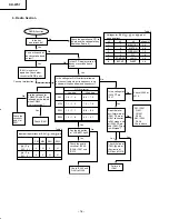
Check the +3 V line.
Check, the oscillator circuit
or IC301 is broken down.
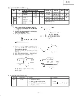
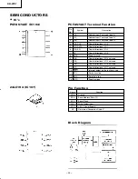
Check "BATT"
display.
Is "BATT"
blinking on
the LCD?
Check Q302, 307
and D318
CN302
Pin
IC301
Pin
<4.2V
BATT
blinks.
Check the AC
voltage or replace
the battery in
case of battery
exhaustion.
Check whether IC301
pin
line is in "H" or not.
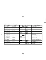
LCD display
Display when the power turns ON without
signal.
eg)
Check after resetting.
WS Function
WS SAT
/
SEARCH
/
AFRST - 1
/
Displaying "NO BEAM"
and the function
FM Function
FM 87.50MHz
Is the voltage to
IC301 pin
3
V?
Is the oscillator circuit of
IC301 and
pin in
operation?
Failure in the oscillator
circuit of IC302
pin for
the LCD driver or in IC302
1. System Check
KH/Pg 10-17 (TroubleSht)
10/11/00, 1:50 PM
10
Summary of Contents for KHWS1W
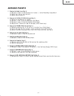
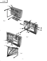
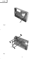
Page 5: ...KH WS1 5 Fig 4 Fig 5 5 6 ...
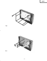
Page 6: ...KH WS1 6 Fig 6 Fig 7 metal pin 7 8 Connector J 9 ...
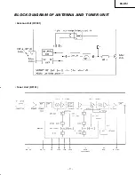
Page 17: ...KH WS1 17 BLOCK DIAGRAM OF ANTENNA AND TUNER UNIT Antenna Unit RF001 Tuner Unit RF101 ...
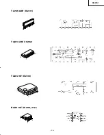
Page 26: ...KH WS1 26 TA7368P IC206 207 BU4066BCF IC204 BA033ST V5 IC209 1 9 7 8 1 14 1 2 3 4 5 ...
Page 28: ...KH WS1 28 TC9298F IC302 ...
Page 32: ...KH WS1 32 SATELLITE P W B TUNER PWB Soldering Side Soldering Side ...
Page 33: ...KH WS1 33 Component Side TUNER PWB SATELLITE P W B Component Side ...
Page 34: ...KH WS1 34 Soldering Side MAIN PWB ...
Page 35: ...KH WS1 35 MAIN P W B Component Side ...
Page 37: ...KH WS1 CIRCUIT DIAGRAM TUNER DTS Circuit 38 37 it A2 10 11 00 1 57 PM 37 ...
Page 38: ...CIRCUIT DIAGRAM ATELLITE Circuit 40 39 it A2 10 11 00 1 57 PM 38 ...
Page 39: ...KH WS1 42 41 BLOCK DIAGRAM Lk Xploded A3 10 11 00 2 00 PM 41 ...
Page 41: ...THE UPDATED PARTS LIST FOR THIS MODEL IS AVAILABLE ON ESTA ...


