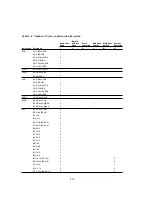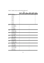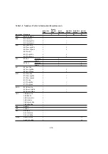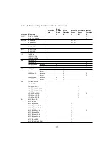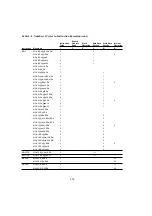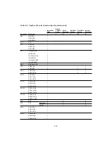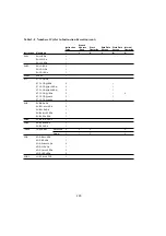
2.6 Number of States Required for Instruction Execution
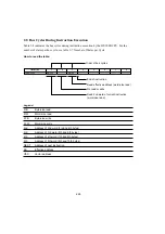
The tables in this section can be used to calculate the number of states required for instruction
execution by the H8/300H CPU. Table 2-8 indicates the number of instruction fetch, data
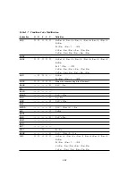
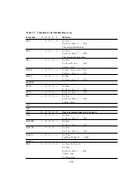
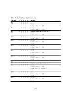
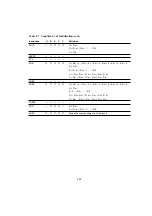
read/write, and other cycles occurring in each instruction. Table 2-7 indicates the number of states
required for each size. The number of states required for execution of an instruction can be
calculated from these two tables as follows:
Execution states = I
×
S
I
+ J
×
S
J
+ K
×
S
K
+ L
×
S
K
+ M
×
S
M
+ N
×
S
N
Examples: Advanced mode, stack located in external memory, on-chip supporting modules
accessed with 8-bit bus width, external devices accessed in three states with one wait state and 16-
bit bus width.
1.
BSET #0, @FFFFC7:8
From table 2-8:
I = L = 2, J = K = M = N= 0
From table 2-7:
S
I
= 4, S
L
= 3
Number of states required for execution = 2
×
4 + 2
×
3 = 14
2.
JSR @@30
From table 2-8:
I = J = K = 2, L = M = N = 0
From table 2-7:
S
I
= S
J
= S
K
= 4
Number of states required for execution = 2
×
4 + 2
×
4 + 2
×
4 = 24
212


