


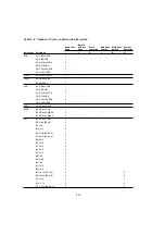

Table 2-2 Instruction Set (cont)
(8) Block Transfer Instructions
Addressing Mode and Instruction Length (bytes)
Condition Code
No. of States
Ad-
Mnemonic
Size #xx Rn @ERn @(d,ERn) @ERn+/@–ERn @aa @(d,PC) @@aa —
Operation
I
H
N
Z V
C
Normal vanced
EEPMOV EEPMOV.B
—
4
if R4L
≠
0
— — — — — —
8+4n
*
2
8+4n
*
2
Repeat @R5
→
@R6
R5+1
→
R5
R6+1
→
R6
R4L–1
→
R4L
Until R4L = 0
else next;
EEPMOV.W
—
4
if R4
≠
0
— — — — — —
8+4n
*
2
8+4n
*
2
Repeat @R5
→
@R6
R5+1
→
R5
R6+1
→
R6
R4L–1
→
R4L
Until R4 = 0
else next;
Notes:
*
1 The number of states is the number of states required for execution when the instruction and its operands are located in
on-chip memory. For other cases see section 2.6, Number of States Required for Execution.
*
2 n is the value set in register R4L or R4.
1
Set to 1 when a carry or borrow occurs at bit 11; otherwise cleared to 0.
2
Set to 1 when a carry or borrow occurs at bit 27; otherwise cleared to 0.
3
Retains its previous value when the result is zero; otherwise cleared to 0.
4
Set to 1 when the adjustment produces a carry; otherwise retains its previous value.
5
The number of states required for execution of an instruction that transfers data in synchronization with the E clock is
variable.
6
Set to 1 when the divisor is negative; otherwise cleared to 0.
7
Set to 1 when the divisor is zero; otherwise cleared to 0.
8
Set to 1 when the quotient is negative; otherwise cleared to 0.
199