7.2 Repair and Servicing
131
1
2
3
4
5
6
7
8
9
10
M
a
in
te
nan
ce an
d S
e
rvi
c
e
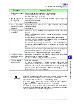
• Displayed values
seem too low
• Is the frequency of the measured current out of the specified
range of either the 3290-10 or clamp-on sensor?
If the carrier frequency of an inverter is high, the displayed value
may be smaller than the total rms value.
❖
See Section 6.4 "Combined Accuracy" (page 122)
• Does the peak value exceed the crest factor specification?
If possible, select a higher current range.
• Does the crest factor (=peak/rms) exceed the specification?
❖
See page 53
Integral Measurement
• The measured current may be too small. Verify the current mea-
surement items on page 130.
• Has measurement been stopped by the automatic timer?
The setting can be viewed by pressing the
button.
• Has a measurement exceeded the current range?
If a measured value exceeds the current range, the maximum dis-
playable value in that range is used in the integration.
❖
See page 74
Duty
• The measured current may be too small. Verify the current mea-
surement items on page 130.
• Is the current threshold properly set?
Verity the current threshold setting (
button).
• Is the time to exceed the threshold too short?
In certain cases, because of the interaction between current
measurement sampling and internal processing, the operating
current may be improperly detected.
❖
See page 82
Frequency Measurement
• Is the measured waveform non-sinusoidal (such as an inverter)?
• Is the measured current at least 5% of the L range?
❖
See page 61
• Output values seem
too low
• Check the same items as for displayed values.
• Is the plug on the Output Cord inserted all the way into the jack?
• Is the Output Cord broken?
❖
See Section 2.4 "Connecting the Output Cords (Optional)" (page 34)
• Is the output selection (REC or MON) correct?
❖
See "Output Settings" (page 54)
• Does the connected instrument employ AC coupling?
Is the filter function enabled?
• Is the filter function of the meter enabled?
Symptom
Items to Check
Summary of Contents for 3290-10
Page 1: ...CLAMP ON AC DC HiTESTER INSTRUCTION MANUAL 3290 10...
Page 2: ......
Page 6: ...iv Contents...
Page 14: ...8 Usage Notes...
Page 42: ...36 2 5 Turning Power On and Off...
Page 54: ...48 3 6 Measuring Duty by Timer...
Page 149: ...4 5 6 7 8 9 10 11...
Page 150: ......


