background image

4

5

6

7

8

9

10

11

Summary of Contents for 3290-10

Page 1: ...CLAMP ON AC DC HiTESTER INSTRUCTION MANUAL 3290 10...

Page 2: ......

Page 3: ...DC HiTESTER 12 1 3 2 Model 9691 9692 9693 CLAMP ON AC DC SENSOR Optional 18 1 4 Buttons Operations 19 1 5 Measurement Modes 20 1 6 Quick References 21 2 Measurement Preparations 27 2 1 Attaching the S...

Page 4: ...arameter 50 4 3 Measuring Current 51 4 4 Measuring Peak Current 62 4 5 Current Integration 66 4 6 Measuring Duty 79 5 Applicable Measurement Modes 89 5 1 Auto Zero Adjustment Function 89 5 2 Display U...

Page 5: ...6 3 1 Model 9691 CLAMP ON AC DC SENSOR 116 6 3 2 Model 9692 CLAMP ON AC DC SENSOR 118 6 3 3 Model 9693 CLAMP ON AC DC SENSOR 120 6 4 Combined Accuracy 122 6 4 1 Models 9691 3290 10 Combined Accuracy...

Page 6: ...iv Contents...

Page 7: ...damage occurred during shipping In particular check the accesso ries panel buttons and jacks If damage is evident or if it fails to operate according to the specifications contact your dealer or Hiok...

Page 8: ...the meter Be certain that you understand the instructions and precautions in the manual before use We disclaim any responsibility for acci dents or injuries not resulting directly from meter defects I...

Page 9: ...and indicated on the measur ing meter dgt resolution The smallest displayable unit on a digital measuring meter i e the input value that causes the digital display to show a 1 as the least significant...

Page 10: ...category than that for which the device is rated could result in a severe accident and must be carefully avoided Never use a CAT I measuring device in CAT II III or IV environ ments The measurement c...

Page 11: ...er is not designed to be entirely water or dust proof Do not use it in an especially dusty environment nor where it might be splashed with liquid This may cause damage Do not use the meter near a sour...

Page 12: ...clamp to a circuit that operates at more than 600V or over bare conductors Clamp sensor should only be connected to the secondary side of a breaker so the breaker can prevent an accident if a short c...

Page 13: ...se 2 wire or three phase 3 wire cables clamped together will not produce any reading OK Handling the Clamp Sensors The ends of the clamp sensor are very delicate Be careful not to drop the sensor or s...

Page 14: ...8 Usage Notes...

Page 15: ...ets up the appropriate range When combined with the 9691 9692 or 9693 Sensor the 3290 10 HiTESTER can perform DC AC and AC DC measurement of a live power line In addition current inte gral and duty me...

Page 16: ...uty measurements Measurement times can be set from one minute to 99 hours 59 minutes Repeating measurements Any timer can be set to perform up to 20 repeated measurements Historical measurement data c...

Page 17: ...s superimposed AC and DC components and full and half wave rectified waveforms Selectable measurement response time Measurement response time can be set to FAST NORMAL or SLOW in AC and AC DC modes Mu...

Page 18: ...SOR to this jack Output Jack 2 OUT2 Connect the optional 9094 OUTPUT CORD to this jack to obtain output during integral measurement Output Jack 1 OUT1 Connect the optional 9094 OUTPUT CORD to this jac...

Page 19: ...function in blue letters allocated to each button is available To turn off press the SHIFT button again Some buttons may be locked when is on Holding the SHIFT button while pressing the button to turn...

Page 20: ...applied to the display AC and AC DC Modes Applies low pass filtering at about 550 Hz to the display and output DC Mode see page 63 Displays positive and negative peak values Peak measurement determin...

Page 21: ...elapsed time from when measurement was started by the START STOP button the timer setting and repetition number alternating once per second Elapsed time timer setting and repetition number Elapsed tim...

Page 22: ...value OUT2 Setting of OUT2 PEAK Wave peak value Data hold function Hz Frequency MON Monitor is active Button lock is active MON FL 1 Hz filter for monitor is active A Current REC Record is active Ah...

Page 23: ...n remove the case to replace the battery Screw Others Top Case Cover the 3290 10 with this case when not in use to protect the LCD buttons and jacks Top Case Clasp Insert the clasp into the top case t...

Page 24: ...18 1 3 Identification of Controls and Indicators 1 3 2 Model 9691 9692 9693 CLAMP ON AC DC SEN SOR Optional Model 9692 Model 9693 Model 9691 Output Connector...

Page 25: ...MAX PEAK MIN MAX PEAK MIN Elapsed time Positive integral Total integral Negative integral Interval mean Integral value current value Interval mean Integral value current value Timer setting time repe...

Page 26: ...g to the waveform shown below 1 5 Measurement Modes Mode Input waveform Display OUTPUT only for current mode REC MON MON FL DC Yes Setting impos sible No Not measurable Average measurement AC No Not m...

Page 27: ...measurement 62 AC measurement 51 AC peak measurement 62 AC DC measurement 51 AC DC peak measurement 62 Hz measurement 51 Measure ment ADJ SHIFT Measure ment PEAK CLEAR ADJ SHIFT Measure ment Measure...

Page 28: ...nt 66 AC interval mean current measurement 66 AC DC integral measurement 66 Measure ment INTEG CLEAR ADJ SHIFT START SHIFT Measure ment INTEG CLEAR ADJ SHIFT START SHIFT AVE Press three times Measure...

Page 29: ...RT SHIFT AVE Measure ment Numerical Entry Display SHIFT Duty Display SHIFT Setting Accept the Setting ADJ SHIFT CLEAR START SHIFT Display the operating time Display the duty Measure ment Numerical Ent...

Page 30: ...9 Low frequency below 10 Hz current measurement 51 92 Measure starting current 51 90 Accept the Setting SHIFT SHIFT Timer Display Numerical Entry Display Setting Accept the Setting SHIFT SHIFT Timer D...

Page 31: ...o measurement value and output Filter Function AC and AC DC modes 95 Store data while TIME is displayed 100 Store settings while TIME is not displayed 101 Recall stored data data recall 103 Output SHI...

Page 32: ...Verify remaining battery charge 105 Suspend display updating TIME is not displayed 96 Button lock 103 Disabling the auto power off function 104 Disabling the beep tone 107 SHIFT Disable HOLD is displ...

Page 33: ...on 2 1 Attaching the Strap page 28 See Section 2 2 Connecting Power page 29 Connecting the Clamp on Sensor See Section 2 3 Connecting the CLAMP ON AC DC SENSOR page 33 Connecting the Output Cords See...

Page 34: ...taching the Strap Using the 3290 10 with the strap attached improves operability 2 1 Attaching the Strap 1 Fasten the two straps together into one 2 Attach each end to the 3290 10 as shown in the figu...

Page 35: ...ernal power When the batteries are installed the 3290 10 will turn on even if the polar ity of the external power is reversed damaging the meter The indicator appears when battery voltage becomes low...

Page 36: ...an inac curate measurement result i e value larger than the actual value may be displayed While operating from the AC adapter the remaining battery charge indicator bar graph indicates the loaded outp...

Page 37: ...ents are 8 4 to 15 6 V DC at 1 2 VA To avoid malfunctions or damage to the meter and electric accidents use only a power source that meets these requirements To avoid electric shock connect the negati...

Page 38: ...In a mobile installation if the device under test is grounded to the vehicle chassis R connect the negative conduc tor to the chassis Make sure the power is turned off before connecting or discon nect...

Page 39: ...he output connector of the clamp on sen sor from the 3290 10 sensor jack be sure to hold it by the metal part and pull it upward Because the connectors lock pulling or twisting the cable can damage th...

Page 40: ...Cords Optional 1 Confirm that the 3290 10 is turned off 2 Remove the dust cap from the output jack and insert the out put cord plug securely Current measurement output OUT 1 Output jack 1 Integral out...

Page 41: ...hows the remaining battery charge 4 The DC measurement mode is enabled Press the button again to turn the meter off 100 remaining battery charge new batteries 50 remaining battery charge 0 remaining b...

Page 42: ...36 2 5 Turning Power On and Off...

Page 43: ...icted cur rent flow could cause a serious accident if a short circuit occurs To avoid damage to the meter do not short circuit the output jacks and do not input voltage to the output jacks The maximum...

Page 44: ...presence of strong electromag netic fields such as near radio transmitters The reading may show a measurement greater than the actual value due to magnetic field interference The amount of inter fere...

Page 45: ...tomatic zero adjustment is displayed 3 Clamp around a conductor to be mea sured so that it is centered in the clamp The figure shows the 9691 CLAMP ON AC DC SENSOR The current direction mark on Models...

Page 46: ...ing current below 10 Hz use the AC DC mode and press SHIFT SAM PLE to set the display update rate measure ment response time to SLOW See Section 5 3 Measurement Response Time page 92 2 Clamp around a...

Page 47: ...ge can be left as AUTO 4 Press SHIFT 0 ADJ to execute automatic zero adjustment is displayed 5 Clamp around a conductor to be mea sured so that it is centered in the clamp The figure shows the 9691 CL...

Page 48: ...minutes Number of repetitions 10 times 1 Press the button to select AC Button presses are ignored if TIME is dis played press to clear it 2 Press button twice to select the H range 200 A 3 Press butto...

Page 49: ...te gral Unless output is required the integrating range can be left as AUTO 10 Clamp around a conductor to be mea sured so that it is centered in the clamp 11 Press SHIFT START STOP to start integral...

Page 50: ...integral value derived from measured current and measurement time is 200 Ah 100 A X 2 h or less OUT1 MON output OUT2 Positive integral output 1 Press the button to select DC Button presses are ignore...

Page 51: ...around a conductor to be mea sured so that it is centered in the clamp The figure shows the 9691 CLAMP ON AC DC SENSOR The current direction mark on Models 9692 and 9693 CLAMP ON AC DC SENSORs is in a...

Page 52: ...rrent Timer 24 hours Repetitions none one time only Blinking Blinking 1 Press the button to select AC Button presses are ignored if TIME is dis played press to clear it 2 Press button to select the L...

Page 53: ...cept the entered values 11 Press the button to display the duty Although no unit indicator appears the displayed value is percentage 12 Clamp around a conductor to be mea sured so that it is centered...

Page 54: ...48 3 6 Measuring Duty by Timer...

Page 55: ...sed If damaged contact your dealer or Hioki representative Model 3290 10 Battery Is the indicator dis played indicates low battery voltage In this state proper measurement may not be possible so the b...

Page 56: ...at the same time A current threshold must be set in order to perform duty measure ment 4 2 Selecting the Measurement Parameter Current Frequency Peak current Duty Integral RATE data duty and operating...

Page 57: ...Measurement No Yes DC AC Hz AC DC SHIFT SHIFT SHIFT SHIFT At 0 A input SHIFT At 0 A input Current Measurement No Yes No Yes Mode Selection Range Selection Range Selection Range Selection Output Setti...

Page 58: ...mponent for display However this filter also slows measurement response so rapid current variations are not detected Low pass filter LPF a filter that passes only low frequencies See Section 5 4 Filte...

Page 59: ...e L range if nothing is being measured When selecting a range both rms and peak values need to be considered For example if the rms current is low but the peak value is high the waveform may be clippe...

Page 60: ...The measured waveform is converted from rms RMS DC conversion for output settable for AC and AC DC modes The response speed can be changed by pressing SHIFT SAMPLE Be sure to select the measurement r...

Page 61: ...range of the meter and that of the connected instrument e g data recorder Conversion tables are shown here Connected Instrument Measuring Range DIV 10 mV 20 mV 50 mV 0 1 V 0 2 V 0 5 V 1 V 2 V 20 A ran...

Page 62: ...de selected Guaranteed output accuracy is applicable to current display values that do not cause O L to be displayed in the L range MON output can be saturated when output exceeds 3 5 V in the L range...

Page 63: ...tment If Auto zero adjustment is not performed the displayed and output current value is always added to measurements Auto zero adjustment is unnecessary in AC mode Auto zero adjustment should be perf...

Page 64: ...ironment with wide temperature variations we suggest being aware beforehand of changes to the zero point with no input However while zero point variations affect DC values they have no effect in the A...

Page 65: ...itry The examples show sensitivity variations normalized to 23 C with temperature change for different sensors characteristics vary slightly from one element to another Specified operating temperature...

Page 66: ...when the con ductor to be measured is centered in the clamp to minimize the effects of conductor proximity to the clamp However if the conductor to be measured is not positioned orthogonally to the c...

Page 67: ...nt For Frequency Measurement When the amplitude of the current being measured is near the bottom of the L range 5 or less of the full range frequency measurement may be incorrect The bar graph indicat...

Page 68: ...lay unnecessary Usable with all wave forms absolute value display Mode Selection Peak Current Measurement Selects Peak Selects Peak Selects Peak Range Selection Range Selection Range Selection Auto Ze...

Page 69: ...e button to select PEAK DC Mode Usable with all waveforms Displays positive and negative peak values AC Mode Usable with AC waveforms with no DC component Displays absolute value AC DC Mode Usable wit...

Page 70: ...00 A L L Low Range When using the 9691 or 9692 20 A When using the 9693 200 A H H High Range When using the 9691 or 9692 200 A When using the 9693 2000 A If the appropriate range cannot be estimated m...

Page 71: ...minimize the effects of conductor proximity to the clamp However if the conductor to be measured is not positioned orthogonally to the clamp on sensor current measurements will be slightly affected a...

Page 72: ...Value Settings Appear Enter Timer Value Repetition Setting Display Enter Number of Repetitions Accept Settings Need Repetition Yes No SHIFT SHIFT SHIFT Preparations for Current Measurement Timer Setti...

Page 73: ...d by pressing the button twice and skip ahead to Integral Value Display page 69 2 Press the button to display the timer If TIME is displayed press the button 3 Press SHIFT INPUT SET to display the num...

Page 74: ...n integral can be measured over a speci fied interval The integration time set on the timer can be repeated up to 20 times For example a 30 minute integration time might be repeated 10 times If you do...

Page 75: ...9 10 Measurement Procedure Integral Value Display 8 Press the button to display the integral 9 Press the button to clear INTEG data integral and interval mean values Clearing INTEG data on the integra...

Page 76: ...ime and current range settings are not displayed even if the button is pressed If no output settings are made the integral range can be changed during integral measurement Integral Range Table Current...

Page 77: ...abled when neither OUT1 or OUT2 is displayed Mode Setting Bar Graph Display OUT2 REC DC Total integral output Positive integral output Negative integral output AC AC DC none Integral output fixed No p...

Page 78: ...he latest mea surement is retained Integral measurement output levels are shown on the meter s battery cover Determine the appropriate output range from the integral range of the meter and the input r...

Page 79: ...connected instrument data recorder or L terminal at the recorder side to earth ground DC mode case Make sure that the direc tion of current flow in the conductor matches that of the arrow on the clamp...

Page 80: ...positive and negative peak val ues Stopping integration also stops the elapsed time count The appearance of the or symbol blinking while an inte gral value is displayed indicates than an over range m...

Page 81: ...tton The repetition number of the occurring measurement is indicated on the bar graph To view historical INTEG data integrals and interval mean values After pressing the button HOLD displayed press th...

Page 82: ...imes 9 times 10 times Start Measurement Timer Setting Repetitions View Data History button Integral and interval mean value button Peak maximum and minimum values After pressing button Data from first...

Page 83: ...ositive integral may be too small although there is no net error in the total integral On the other hand this meter splits the waveform into positive and negative components before processing Each pol...

Page 84: ...ear PEAK data button disabled Change timer setting SHIFT INPUT SET button disabled Change output settings SHIFT OUTPUT button disabled Change display update rate SHIFT SAMPLE button disabled Auto zero...

Page 85: ...ctor Timer Setting Expired Stop Measurement Measurement Stops Automatically Timer Settings Needed Duty Measurement Time Display Appears Value Settings Appear Enter Timer Value Repetition Setting Displ...

Page 86: ...he 9691 9692 and 9693 CLAMP ON AC DC SENSORs See Sensor Temperature Characteristics page 58 Current Threshold Setting 2 Press the button to display the duty If TIME is displayed press button to clear...

Page 87: ...gn disap pears In AC and AC DC modes setting are made with rms positive polarity In DC mode the setting may be positive or negative for exam ple when the threshold is set to 20 A and 10 A is measured...

Page 88: ...surement In AC and AC DC modes measurement response time is affected by RMS DC conversion If severe current fluctuations at 45 Hz and above are present we recommend measuring in FAST mode Timer Settin...

Page 89: ...o accept your settings Blinking Blinking Blinking By using the timer an integral can be measured over a speci fied interval The integration time set on the timer can be repeated up to 20 times For exa...

Page 90: ...measurements are obtained when the con ductor to be measured is centered in the clamp to minimize the effects of conductor proximity to the clamp However if the conductor to be measured is not positi...

Page 91: ...percentage Operat ing Time Measurement Time X 100 operating time and cur rent threshold Duty Percentage Operating Time Current Threshold Although the percent sign is not displayed the displayed duty v...

Page 92: ...ing measurement Press the button The repetition number of the occurring measurement is indicated on the bar graph To view history of RATE data Duty and Operating Time After pressing the button HOLD di...

Page 93: ...Data from second measurement Data from ninth measurement Data from tenth measurement Total data Total data from first through tenth measurements 30 min 30 min 30 min 30 min 30 min Once 2 times 3 times...

Page 94: ...g SHIFT INPUT SET button disabled Change timer setting SHIFT INPUT SET button disabled Change output settings SHIFT OUTPUT button disabled Change display update rate SHIFT SAMPLE button disabled Auto...

Page 95: ...urement Modes 5 5 1 Auto Zero Adjustment Function Before Adjustment Finished Because the zero suppression function may be enabled forc ing counts of five or less to display as zero perform auto zero a...

Page 96: ...d 1 Press SHIFT SAMPLE 2 The display update rate changes as follows 5 2 Display Update Rate FAST SLOW NORMAL The measurement response time rms measurement conver sion speed is affected by this selecti...

Page 97: ...is fast and measurement response is slow range changes are delayed An error also occurs in MAX and MIN dis played values Therefore if the measured current is expected to change manu ally select the H...

Page 98: ...AUTO ranging and the range switches automatically in response to a change in measured cur rent current measurement is temporarily inhibited because the display update is fast and measurement response...

Page 99: ...sing Edge 100 A 200 A AC mode 200 A range 0 A 180 A 45 Hz 0 2 s 100 A 200 A AC mode 200 A range 0 A 180 A 10 Hz 100 A 200 A AC DC mode 200 A range 0 A 180 A 1 Hz 0 8 s 8 s FAST NORMAL SLOW Input wavef...

Page 100: ...AC mode 200 A range 200 A 20 A 45 Hz 0 2 s AC mode 200 A range 200 A 20 A 10 Hz AC DC mode 200 A range 200 A 20 A 1 Hz 0 8 s 8 s FAST NORMAL SLOW Input waveform OUT 1 REC output waveform Input wavefo...

Page 101: ...function is useful if noise or ripple is present on DC current The displayed value is always passed through another low pass filter of about 0 5 Hz AC and AC DC Modes Press SHIFT FILTER so that FILTE...

Page 102: ...displayed and the display is suspended To resume normal display activity press again 5 5 Data Hold During integral and duty measurement pressing the button does not interrupt integration or elapsed ti...

Page 103: ...e sequential number of the cur rently displayed measurement To view RATE duty and operating time data history 1 After pressing the button during repeating measure ment press the button 2 The bar graph...

Page 104: ...through tenth measurements 30 min 30 min 30 min 30 min 30 min Once 2 times 3 times 9 times 10 times Start Measurement button Integral and interval mean value button Peak maximum and minimum values Se...

Page 105: ...B2 C2 Ai Bi Ci A20 B20 C20 An Bn Cn Positive Integral Ah B1 B2 Bi B20 Bn Negative Integral Ah C1 C2 Ci C20 Cn Interval Mean Value A D1 A1 S D2 A2 S Di Ai S D20 A20 S Dn An S RATE Data Duty E1 F1 S X...

Page 106: ...nimum values To Erase Stored Data 1 Hold the button while pressing the button to turn the meter on 2 and are displayed and the data is erased To Recall Stored Data See Section 5 9 Recalling Stored Dat...

Page 107: ...d However auto zero adjustment should always be performed before measuring with DC and AC DC modes Auto power off and beeper settings can be saved When the auto power off function is enabled or the be...

Page 108: ...al Data page 97 This function locks deactivates buttons including the but ton to prevent changing settings The auto power off function is disabled 1 Press SHIFT LOCK 2 is displayed and the button lock...

Page 109: ...eration by 10 minutes The Auto Power off is Enabled To Disable the Auto Power Off Function 1 Hold the button while pressing the button to turn the meter on 2 The auto power off function is disabled To...

Page 110: ...the indicator low battery warning is dis played 5 12 Battery Checking New battery 50 remaining charge 0 remaining charge is displayed and three beeps sound Meter accuracy is not guaranteed when the in...

Page 111: ...can be viewed on the display imme diately upon turning the meter on It can also be viewed on the bar graph by pressing SHIFT B CHECK However because the remaining battery charge indication is merely...

Page 112: ...beeper is disabled To re enable the beeper press the button to turn the meter off and back on 5 14 Beeper When the beeper has been disabled and settings have been saved the settings must first be retu...

Page 113: ...t Specifications 107 1 2 3 4 5 6 7 8 9 10 Specifications Measurement items are as follows DC AC AC DC Hz Frequency Current Integral Duty Percentage and Operating Time Specifications 6 6 1 Measurement...

Page 114: ...and negative polarities displayed AC and AC DC Modes Absolute value display Maximum Minimum Value Measurement AC and AC DC modes only Maximum and minimum current measurement values are retained Outpu...

Page 115: ...DC 0 3 5 AC AC DC FAST 0 3 7 AC DC only 0 3 3 0 3 3 NORMAL 0 3 3 SLOW 1 0 3 AC DC only rdg mV DC 1 to 10 Hz 10 to 45 Hz 45 to 66 Hz 66 to 1 kHz AC DC FAST 0 8 10 AC DC only 0 8 5 0 8 5 NORMAL 0 8 5 SL...

Page 116: ...tically Internal Ranges 10 00 100 0 and 1000 Hz Accuracy When input is 5 or larger of the current range DIsplay Accuracy rdg dgt Range Accuracy Range Resolution Maximum Display 10 Hz 1 00 to 12 50 Hz...

Page 117: ...gral data is retained TIME displayed the data is saved upon auto power off Data saving when battery charge is depleted Data saving overwriting method by holding the button for two seconds View repeati...

Page 118: ...is 5 counts Measurement start stop and data clear button operations Measurement stop by timer setting from 1 min to 99 hours and 59 min in minute steps Repeating timer measurements 1 to 20 times Elaps...

Page 119: ...550 Hz 10 display and output Setting the save function Hold down the button for more than 2 sec to save the current settings To initialize hold down the button and turn on the button Button lock Press...

Page 120: ...te at 23 C 73 F Digital counter Bar graph display Circuit dynamic characteristics crest factor Max 2 5 The upper limit of H range is the maximum peak current of the sen sor connected The maximum outpu...

Page 121: ...4 to 15 6 V DC external power Maximum rated power 1 2 VA with AC adapter and sensor connected 500 mVA with batteries and sensor connected Battery life Approx 22 hours continuous no load with a sensor...

Page 122: ...400 A m Temperature characteristics 0 to 40 C range 0 1 x accuracy specifications C 32 to 104 F range 0 18 x accuracy specifications F Location for use Indoor altitude up to 2000 m 6566 feet Operatin...

Page 123: ...ted Transient Overvoltage 6000 V Pollution Degree 2 EMC EN61326 Continuous Input Range DC to 66 Hz 66 to 500 Hz 0 to 80 A 1 0 rdg 0 5 mV 1 0 rdg 0 5 mV 2 0 rdg 0 5 mV 80 to 100 A 2 5 rdg 0 5 mV Peak I...

Page 124: ...04 F range 0 18 x accuracy specifications F Location for use Indoor altitude up to 2000 m 6566 feet Operating temperature and humidity range 0 to 40 C 32 to 104 F 80 RH or less no condensation Storage...

Page 125: ...lution Degree 2 EMC EN61326 Continuous Input Range DC to 66 Hz 66 to 1 kHz 0 to 200 A 1 0 rdg 0 5 mV 1 0 rdg 0 5 mV 2 0 rdg 0 5 mV Peak Input Range DC to 66 Hz 66 to 1 kHz 0 to 300 A 1 0 rdg 2 mV 1 0...

Page 126: ...F range 0 18 x accuracy specifications F Location for use Indoor altitude up to 2000 m 6566 feet Operating temperature and humidity range 0 to 40 C 32 to 104 F 80 RH or less no condensation Storage te...

Page 127: ...Input Range DC to 66 Hz 66 to 500 Hz 0 to 1800 A 1 5 rdg 0 5 mV 1 0 rdg 0 5 mV 2 0 rdg 0 5 mV 1800 to 2000 A 2 0 rdg 0 5 mV Peak Input Range DC to 66 Hz 66 to 500 Hz 0 to 2300 A 1 5 rdg 2 mV 1 0 rdg...

Page 128: ...A DC 1 to 10 Hz 10 to 66 Hz 66 to 500 Hz L DC 1 3 0 10 A AC DC 1 3 0 12 A 2 0 0 08 A 1 3 0 08 A 2 3 0 08 A AC H DC 1 3 0 5 A AC DC to 80 A 1 3 0 7 A 2 0 0 3 A 1 3 0 3 A 2 3 0 3 A 80 to 100 A 2 8 0 3 A...

Page 129: ...to 500 Hz L DC AC DC 1 3 10 mV 2 3 10 mV AC H DC AC DC to 80 A 1 3 5 5 mV 2 3 5 5 mV 80 to 100 A 2 8 5 5 mV AC to 80 A 2 3 5 5 mV 80 to 100 A 2 8 5 5 mV rdg A DC 1 to 10 Hz 10 to 66 Hz 66 to 500 Hz L...

Page 130: ...0 08 A AC H DC 1 3 0 5 A AC DC 1 3 0 7 A 2 0 0 3 A 1 3 0 3 A 2 3 0 3 A AC rdg mV DC 1 to 10 Hz 10 to 66 Hz 66 to 1 kHz L AC DC 1 8 15 mV 2 3 10 mV 1 8 10 mV 2 8 10 mV AC H AC DC 1 8 10 5 mV 2 3 5 5 mV...

Page 131: ...1 3 3 A 2 3 3 A 1800 to 2000 A 2 3 3 A rdg mV DC 1 to 10 Hz 10 to 45 Hz 45 to 66 Hz 66 to 1 kHz L AC DC 2 3 15 mV 3 3 10 mV 2 8 10 mV 1 8 10 mV 2 8 10 mV AC H AC DC to 1800 A 2 3 10 5 mV 3 3 5 5 mV 2...

Page 132: ...A x 1 3 Total error when REC output is 1 2 V 60 Hz for L range Total error 1 8 rdg 10 mV 3 21 6 mV 10 mV 4 31 6 mV True value of 1 2 V output 1 1684 V to 1 2316 V 11 684 A to 12 316 A in terms of curr...

Page 133: ...ion and repair of this meter should be performed only under the supervision of qualified technicians knowledgeable about the dangers involved If the protective functions of the meter are damaged eithe...

Page 134: ...stocking period for replacement parts is five years after end of production When transporting the meter use the original packing materials in which it was shipped and pack in a double carton Damage o...

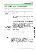
Page 135: ...ction 2 2 3 Using External Power page 31 When using batteries Are the batteries discharged Replace if discharged Have the batteries passed their expiration date Even if batteries have not been used th...

Page 136: ...ensor close tightly If not measurements will be too low Is the intended measurement mode selected See Section 1 5 Measurement Modes page 20 Has auto zero adjustment been performed correctly in DC and...

Page 137: ...dis playable value in that range is used in the integration See page 74 Duty The measured current may be too small Verify the current mea surement items on page 130 Is the current threshold properly s...

Page 138: ...ould cause the displayed value to be too high Frequency Measurement Is a strong ambient magnetic field RF field or noise Is the measured current at least 5 of the L range Is the measured waveform non...

Page 139: ...out put Does the selected display update rate measurement response time suit the frequency of the current to be measured See Section 5 3 Measurement Response Time page 92 The 3290 10 turns off and da...

Page 140: ...requires repair Error No Contents Solution E 001 ROM Checksum Error in the one chip internal microcontroller A component requires replace ment Contact your dealer or Hioki representative E 002 RAM R...

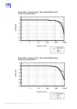
Page 141: ...cable may result in a larger value being dis played when no or low input is made due to noise When using an extension cable note that the accuracy will be within the specifications but the frequency c...

Page 142: ...s Model 9693 extension cable Model 3290 10 MON output frequency characteristics 30 25 20 15 10 5 0 5 1 10 100 1000 10000 100000 Hz GAIN dB Frequency Hz GAIN dB Standard 10 m 100 m 30 25 20 15 10 5 0 5...

Page 143: ...cribed below Model 3290 10 CLAMP ON AC DC HiTESTER 1 Model 9691 CLAMP ON AC DC SENSOR 1 Model 9692 CLAMP ON AC DC SENSOR 1 Model 9693 CLAMP ON AC DC SENSOR 1 Model 9094 OUTPUT CORD 2 Model 9445 02 AC...

Page 144: ...er from the meter 4 Connect the clamp on sensor to the meter 5 Close the carrying case cover 6 Start measuring Model 3290 10 Carrying Case Cover Sensor Cable Top Cover Carrying Case Cover When closing...

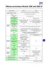
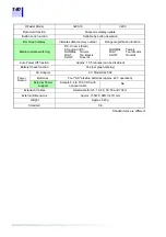
Page 145: ...n off MON output of DC and AC DC 1 Hz settable on off Output 1 Selectable current waveform 2 VDC range or current recording 2 VDC range Output 2 Integral D A output Selectable current recording or low...

Page 146: ...Once 3s NORMAL Twice s FAST Four times s SLOW Once 3s Auto Power Off function Approx 10 5 minutes can be disabled Battery Check function Yes bar graph display Power Source AC Adapter 9 V Model 9445 02...

Page 147: ...Continuous measurement 86 Crest factor 53 114 Cumulative integration 75 Current threshold 15 46 80 D D A output 71 Data hold 96 DC 20 39 Derating 117 119 121 Display update 13 Display update rate 90 1...

Page 148: ...P PEAK 14 19 Peak current 62 PEAK data 97 100 Peak value 14 POWER 13 Power 13 35 115 Q Quick reference 21 R RANGE 14 19 RATE 15 19 RATE data 97 100 Recalling 102 Recalling stored data 102 Record 54 Re...

Page 149: ...4 5 6 7 8 9 10 11...

Page 150: ......

Page 151: ...1 268 28 0568 E mail os com hioki co jp URL http www hioki co jp Printed in Japan 3290B981 04 All reasonable care has been taken in the production of this manual but if you find any points which are u...

Page 152: ...2 Japan TEL 81 268 28 0562 FAX 81 268 28 0568 E mail os com hioki co jp URL http www hioki co jp HIOKI USA CORPORATION 6 Corporate Drive Cranbury NJ 08512 USA TEL 1 609 409 9109 FAX 1 609 409 9108 329...

Reviews: