


Mobile Network Video Recorder User Manual
68
Chapter 9
Device Maintenance
9.1
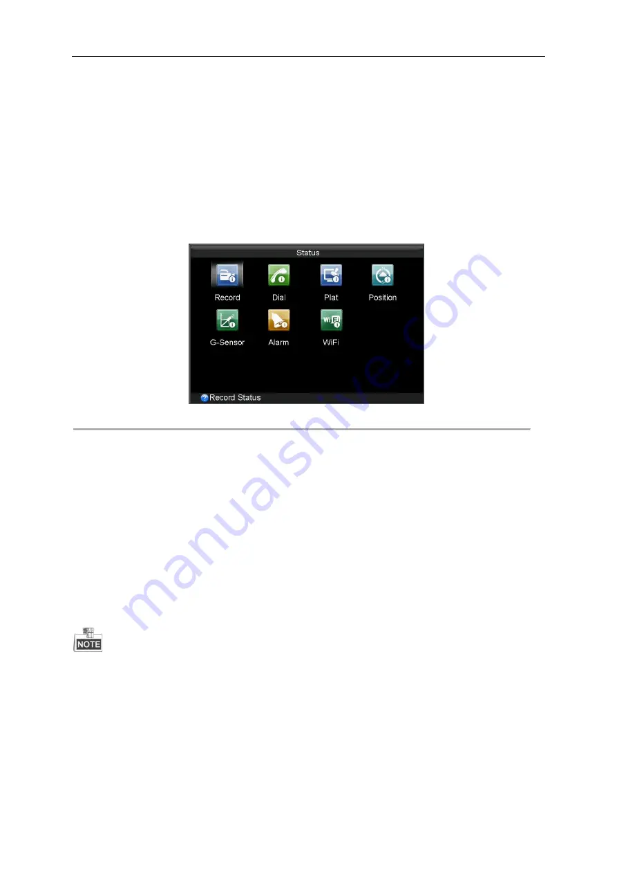
Checking Status
The status of recording, 3G, platform, satellite positioning, G-Sensor, alarm and WiFi can be checked in the Status interface
(Menu>Status).
Figure 9. 1
Status Interface
9.2
Management and Maintenance
9.2.1
Upgrading the System
Purpose:
The mobile NVR can be upgraded by local USB device or remote FTP server.
Upgrading by local USB flash disk
Before you start:
Connect the USB device, on which the upgrade firmware is stored, to the mobile NVR.
The upgrade firmware should be stored in the root directory of the USB device.
Steps:
1.
Enter the Upgrade interface and select USB Upgrade as the upgrade type.
Menu>Maintenance>Upgrade
Summary of Contents for DS-M5504HNI Series
Page 1: ...User Manual UD 6L0204D1120A01 Mobile Network Video Recorder...
Page 47: ...Mobile Network Video Recorder User Manual 46 Figure 4 9 Search Result Interface...
Page 51: ...Mobile Network Video Recorder User Manual 50 Figure 5 6 Wi Fi Status Interface...
Page 53: ...Mobile Network Video Recorder User Manual 52 Figure 6 2 Push Mode Platform...
Page 78: ...User Manual of Mobile Digital Video Recorder 77...


