background image

CoaXPress Area Scan Camera

·

User Manual


81 


2.


Click 

  to select update files (.dav files) in the local PC. 

3.


Click Update to start updating. 


The camera will reboot after updating. 


Update Firmware via USB Interface 

Steps: 

1.


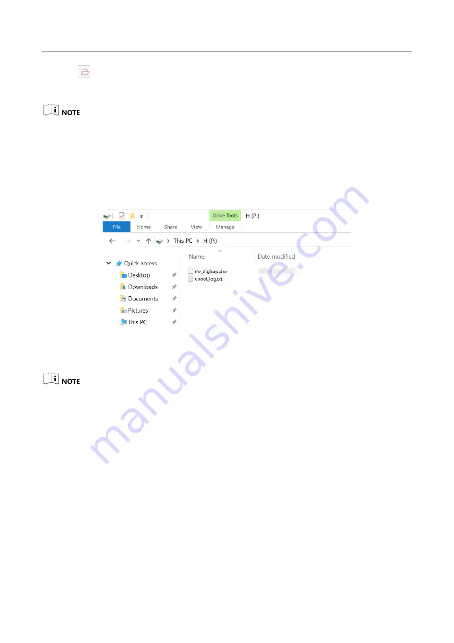
Power on the camera, and connect the camera to the PC via USB data cable. 

2.


Copy the dav file of the camera into the added disk. 


Figure 12-9


Copy Files 

3.


Reboot the camera to update firmware. 


The USB data cable you use should have data transmission function. If the USB data cable 
cannot transmit data, the PC will not find the disk. 


Do not power off the camera during firmware updating. If the camera is powered off, format 
disk manually first and then update firmware again. 


Summary of Contents for CoaXPress

Page 1: ...CoaXPress Area Scan Camera User Manual ...

Page 2: ...ILL HIKROBOT BE LIABLE TO YOU FOR ANY SPECIAL CONSEQUENTIAL INCIDENTAL OR INDIRECT DAMAGES INCLUDING AMONG OTHERS DAMAGES FOR LOSS OF BUSINESS PROFITS BUSINESS INTERRUPTION OR LOSS OF DATA CORRUPTION OF SYSTEMS OR LOSS OF DOCUMENTATION WHETHER BASED ON BREACH OF CONTRACT TORT INCLUDING NEGLIGENCE PRODUCT LIABILITY OR OTHERWISE IN CONNECTION WITH THE USE OF THE PRODUCT EVEN IF HIKROBOT HAS BEEN ADV...

Page 3: ...ce will not occur in a particular installation If this equipment does cause harmful interference to radio or television reception which can be determined by turning the equipment off and on the user is encouraged to try to correct the interference by one or more of the following measures Reorient or relocate the receiving antenna Increase the separation between the equipment and receiver Connect t...

Page 4: ...ention The symbols that may be found in this document are defined as follows Symbol Description Provides additional information to emphasize or supplement important points of the main text Indicates a potentially hazardous situation which if not avoided could result in equipment damage data loss performance degradation or unexpected results Indicates a hazard with a high level of risk which if not...

Page 5: ...y cold dusty environment corrosive environment or high humidity environment Do not aim the device lens at objects of strong light such as the sun and incandescent lamp Otherwise the lens may be damaged The device should be stored in dry environment without corrosive gas Avoid placing the device in direct sunlight and poorly ventilated locations or near heat sources such as heater or heating ignori...

Page 6: ... device no components can be maintained by user do not disassemble the device arbitrarily Cleaning Do not touch the image sensor directly If the sensor needs to be cleaned use a clean rag and wet it with alcohol then gently wipe off the dirt if the device is not in use cover the image sensor with dust cover for protection Installation Do not install the device on vibrating surface or places that a...

Page 7: ... Installation Preparation 9 4 2 Install Camera and Connect Frame Grabber 9 Chapter 5 Camera Connection 11 5 1 Intsall Frame Grabber Software 11 5 2 Install MVS Client Software 11 5 3 Connect Camera to MVS Client Software 13 Chapter 6 Client Software Layout 14 Chapter 7 Camera Features 16 7 1 Global Shutter 16 7 2 Rolling Shutter 16 7 3 Sensor Shutter Mode 17 7 4 Overlap Exposure 18 Chapter 8 Image...

Page 8: ...erter 32 9 2 2 Enable Strobe Signal 33 Chapter 10 I O Electrical Feature and Wiring 37 10 1 I O Electrical Feature 37 10 1 1 Line 0 Opto isolated Input Circuit 37 10 1 2 Line 1 Opto isolated Output Circuit 38 10 1 3 Line 2 Bi direction I O Circuit 39 10 2 I O Wiring 42 10 2 1 Line 0 Wiring 42 10 2 2 Line 1 Wiring 43 10 2 3 Line 2 Wiring 44 Chapter 11 Image Parameter 47 11 1 View Resolution 47 11 2...

Page 9: ...9 11 23 3 FFC Correction 70 11 23 4 User PRNUC Correction 71 11 23 5 Other Corrections 71 Chapter 12 Other Functions 73 12 1 Device Control 73 12 2 File Access Control 75 12 3 Save and Load User Set 76 12 4 Transport Layer Control 78 12 5 CoaXPress Parameters 78 12 6 Update Firmware 80 Chapter 13 FAQ 82 13 1 Why the client software is stuck when listing cameras 82 13 2 Why the client software turn...

Page 10: ...CoaXPress Area Scan Camera User Manual x Appendix A Camera Parameter Index 85 ...

Page 11: ...oftware or SDK based on CoaXPress frame grabber 1 2 Key Feature Provides high dynamic range Signal Noise Ratio SNR and high quality image Supports auto and manual adjustment for gain exposure time Look Up Table LUT Gamma correction etc Adopts CoaXPress interface to transmit data Compatible with CoaXPress Protocol and GenlCam Standard The camera functions may differ by models For specific camera fu...

Page 12: ...ture around environment temperature to ensure the normal operation of the camera For specific appearance and dimension please refer to the camera s specification for details The appearance is subject to change and the actual device you purchased shall prevail Figure 2 1 Appearance Type I Figure 2 2 Appearance Type II Figure 2 3 Appearance Type III ...

Page 13: ...CoaXPress Area Scan Camera User Manual 3 Figure 2 4 Appearance Type IV Figure 2 5 Appearance Type V Figure 2 6 Appearance Type VI Figure 2 7 Appearance Type VII ...

Page 14: ...nnector It refers to the 12 pin P10 connector that provides power input output signal etc 5 CoaXPress Interface It refers to the 4 CoaXPress interfaces for transmitting data 6 Fan or TEC For type I II IV V and VI cameras they uses fan to cool For type III camera it uses TEC inside the camera to cool Type VII and type VIII cameras do not have a fan or TEC 7 Camera Indicator It indicates the camera ...

Page 15: ...n Definitions Regarding the type I and type II cameras read the table below to get their pin definitions You should refer to the table below and the label attached to the power and I O cable to wire the device Table 3 1 First Type of Pin Definitions No Signal I O Signal Source Description 1 GND Line 2 Camera power supply ground 2 DC_PWR Camera power supply 3 Reserved 4 Reserved 5 GND_IO Line 0 1 O...

Page 16: ... 3 DC_PWR Camera power supply 4 OPT_IN Line 0 Opto isolated input signal ground 5 OPT_OUT Line 1 Opto isolated output signal ground 6 GND Camera power supply ground 7 GND Camera power supply ground 8 RS 232_RXD RS 232 receives 9 RS 232_TXD RS 232 transmits 10 GPIO2 Line 2 Input or output 11 OPT_OUT Line 1 Opto isolated output 12 OPT_IN Line 0 Opto isolated input 3 2 Indicator Description The camer...

Page 17: ... status of CoaXPress linking indicator When the indicator is flashing rapidly flashing slowly or flashing very slowly its unlit interval is 0 08 s 1 s and 2 s respectively Table 3 4 CoaXPress Linking Indicator Cameras with CXP 6 Interface No Status Description 1 Unlit No CoaXPress linking connected or connection error occurs 2 Solid green CoaXPress linking connected without data transmission or da...

Page 18: ...he camera system is starting 4 Slow flashing orange The camera is acquiring images in trigger mode 5 Rapid flashing orange The camera is connected with the PC and data is being transferred 6 Solid green The camera is connected with the PC but no data is being transferred 7 Rapid flashing green The camera is acquiring images in continuous mode ...

Page 19: ...ately in accordance with camera lens mount 6 Lens Adapter 1 If other lens are used you need to purchase lens adapter separately In order to ensure the normal operation of the camera you need to make sure that the output voltage of DC power supply meets with that of the camera For specific camera voltage range please refer to the specification of the camera 4 2 Install Camera and Connect Frame Grab...

Page 20: ...CXP 2 and CXP 3 It is recommended to install the CoaXPress frame grabber into a free PCIe x 16 slot of the PC Steps 1 Fix the camera to the installation position 2 Install the lens to the camera body 3 Connect the camera to CoaXPress frame grabber via CoaXPress cable 4 Connect the camera to a suitable power adapter via 12 pin power and I O cable ...

Page 21: ...o to the PC s device manager to check if the installation is correct If the frame grabber driver is not installed correctly the MVS client software cannot enumerate and find cameras Refer to the user manual of the frame grabber you purchased for frame grabber installation and operation 5 2 Install MVS Client Software MVS client software is used to connect and set camera parameters and acquire imag...

Page 22: ...rea Scan Camera User Manual 12 Figure 5 1 Installation Interface 4 Click Start Setup Figure 5 2 Default Settings 5 Keep default settings and click Next 6 Finish the installation according to the interface prompts ...

Page 23: ...ouble click MVS client software to run it 2 Click beside GenTL in the device list and click OK in the popup window Figure 5 3 Refresh List 3 Open the cti file according to prompts and the MVS client software will search cameras 4 Double click the camera to connect it to the MVS client software ...

Page 24: ...to the actual one you got Table 6 1 Description of Main Window No Area Name Description 1 Menu Bar The menu bar displays function modules including File View Settings Tool and Help 2 Control Toolbar The control toolbar provides quick operations for the device 3 Device List Panel This panel displays device list and you can connect or disconnect device modify device IP address etc 4 Device Informati...

Page 25: ... interest test pattern etc Acquisition Control You can view and set the camera s acquisition mode frame rate trigger mode exposure time etc Analog Control You can view and set the camera s analog signal including gain black level Gamma correction sharpness etc Color Transformation Control You can view and set the device s color transformation related parameters like hue and saturation LUT Control ...

Page 26: ...time Line 1 Line 2 Line 3 Line 4 Line 5 Line n Line n 1 Readout Readout Exposure Figure 7 1 Global Shutter 7 2 Rolling Shutter For camera that supports rolling shutter as soon as the exposure ends the data readout starts simultaneously After the whole action the rest of rows start to expose and read out one by one All pixels expose at the same time then readout at different time Line 1 Line 2 Line...

Page 27: ...e of the camera s electronic shutter The shutter mode refers to the way in which the image data is captured and processed In general there are 2 sensor shutter modes including Global Reset and Rolling Global reset means that all of the sensor s pixels start exposing at the same time but stop exposing at different time Figure 7 3 Global Reset Rolling means that the camera exposes the pixel rows one...

Page 28: ...he current frame starts to expose simultaneously Overlap Exposure under Internal Trigger Mode Sensor exposure Exposure 1 Exposure 2 Exposure 3 Frame 1 Readout Frame 2 Readout Figure 7 5 Internal Trigger Overlap Exposure Overlap Exposure under External Trigger Mode Sensor exposure Exposure 1 Exposure 2 Exposure 3 Trigger_in 1 Trigger_in 2 Trigger_in 3 Frame 1 Readout Frame 2 Readout Figure 7 6 Exte...

Page 29: ...ports is t and when the configured exposure time is larger than t the less the exposure time the higher the frame rate will be When the configured exposure time is less than or equal to t exposure time will not influence the frame rate Bandwidth The larger the bandwidth the higher the frame rate will be Pixel format The more bytes pixel format occupy the lower the frame rate will be Click Acquisit...

Page 30: ...e number per second You can stop camera image acquisition manually Click Acquisition Control Acquisition Mode and select Continuous or SingleFrame according to actual demands Figure 8 2 Set Acquisition Mode 8 3 Set Trigger Mode The camera has 2 types of trigger modes including internal trigger mode and external trigger mode Internal trigger mode The camera acquires images via its internal signals ...

Page 31: ...gger Selector Trigger Source Software The software sends trigger signal to the camera via CoaXPress interface to acquire images Hardware Trigger Acquisition Control Trigger Selector Trigger Source Line 0 Line 2 External device connects camera via camera I O interface External device sends trigger signal to camera to acquire images Counter Trigger Acquisition Control Trigger Selector Trigger Source...

Page 32: ...s Trigger Mode 3 Select Software as Trigger Source and click Execute in Trigger Software to send trigger commands Figure 8 5 Set Software Trigger 8 4 3 Set Hardware Trigger The camera has one opto isolated input Line 0 and one bi directional I O Line 2 that can be configured as input signal Here we take Line 2 as an example to introduce the hardware trigger settings You select Line 0 or Line 2 as ...

Page 33: ... Figure 8 6 Set Line 2 as Input Signal 3 Select Line 2 as Trigger Source Figure 8 7 Set Hardware Trigger 8 4 4 Set Counter Trigger The counter trigger provides frequency division to the external trigger signal You can set counter trigger as shown below 1 Click Acquisition Control Trigger Selector 2 Select On as Trigger Mode 3 Select Counter 0 as Trigger Source ...

Page 34: ...elects the signal source of counter trigger Line 0 Line 2 or Link Trigger 0 is available This parameter is disabled by default Counter Reset Source Read and write It selects the signal source of resetting counter Software is available only This parameter is disabled by default Counter Reset Write is available under certain condition It resets counter and it can be executed when selecting Software ...

Page 35: ...l prevail 8 4 5 Set Link Trigger The camera supports trigger via CoaXPress frame grabber and you can set related parameters as follows Steps 1 Click Acquisition Control Trigger Selector 2 Select On as Trigger Mode 3 Select Link Trigger 0 as Trigger Source Figure 8 10 Set Link Trigger For more details about frame grabber trigger please refer to the user manual of frame grabber you purchased ...

Page 36: ...lect Anyway as Trigger Source Figure 8 11 Set Free Trigger 8 5 Trigger Related Parameters Under external trigger mode you can set burst frame count trigger delay trigger cache enable trigger activation and trigger debouncer Different trigger sources can set various trigger parameters and their relation is shown below Table 8 3 Trigger Source and Trigger Parameter Sources Parameters Software Trigge...

Page 37: ... is from 1 to 1023 Figure 8 12 Set Burst Frame Count When Acquisition Burst Frame Count is 1 it is in single frame trigger mode When Acquisition Burst Frame Count is larger than 1 it is in multi frame trigger mode If Acquisition Burst Frame Count is n and when inputting 1 trigger signal the camera stops acquiring images after exposing n times and outputs n frame images The sequence diagram of burs...

Page 38: ...e Diagram Here we take the rising edge as the trigger signal You can set Trigger Delay according to actual demands and its range is from 0 μs to 16000000 μs Figure 8 15 Set Trigger Delay 8 5 3 Set Trigger Cache Enable The camera has the function of Trigger Cache Enable During the triggering process if the camera receives new trigger signal it will save and process the signal if you enable this fun...

Page 39: ...ra will delay this exposure time Thus making sure this exposure time is not earlier than the camera s last frame creation time of the 1st trigger signal 8 5 4 Set Trigger Activation The camera supports trigger acquisition in the rising edge falling edge level high level low or any edge of the external signal The principle and parameter of trigger activation are as follows Click Acquisition Control...

Page 40: ...n image acquisition status Level Low Acquisition Control Trigger Activation Level Low If level signal given by external devices is in level low the camera is in image acquisition status 8 5 5 Set Trigger Debouncer The external trigger input signal of the camera may have signal bounce that may cause false trigger Thus it is necessary to debounce the external trigger signal and its sequence diagram ...

Page 41: ...CoaXPress Area Scan Camera User Manual 31 Figure 8 18 Set Trigger Debouncer ...

Page 42: ...ne selector according to actual demands Click Digital IO Control select Line 2 as Line Selector and select Strobe as Line Mode Figure 9 1 Set Line 2 as Output Signal 9 2 Set Output Signal The output signal of the camera is switch signal that can be used to control external devices such as light source PLC etc 9 2 1 Enable Line Inverter Click Digital IO Control Line Selector select line for Line Se...

Page 43: ...ce Description No Name Description 1 Exposure Start Active It refers to output one I O edge signal when starting exposure 2 Acquisition Start Active It refers to output one I O edge signal when starting acquisition 3 Acquisition Stop Active It refers to output one I O edge signal when stopping acquisition 4 Frame Burst Start Active It refers to output one I O edge signal when starting triggering a...

Page 44: ...It refers to output one I O edge signal when timer output is enabled If Timer Active is selected as Line Source you can set Strobe Line Duration and Strobe Line Delay and the camera will output signal correspondingly after click Execute in Line Trigger Software Figure 9 4 Set Timer Active Regarding strobe signal you can also set its duration delay and pre delay Set Strobe Line Duration After enabl...

Page 45: ...be Line Delay and enter Strobe Line Delay according to actual demands Figure 9 6 Set Strobe Line Delay The sequence diagram of strobe line delay is shown below Strobe Trigger_in 1 Sensor Exposure Exposure 1 Exposure 2 Exposure 3 Strobe delay Trigger_in 2 Trigger delay Trigger_in 3 Trigger delay Duration Trigger delay Figure 9 7 Sequence Diagram of Strobe Line Delay Set Strobe Line Pre Delay The ca...

Page 46: ...y The sequence diagram of strobe line pre delay is shown below Strobe Trigger_in 1 Sensor Exposure Exposure 1 Exposure 2 Exposure 3 Trigger delay Trigger_in 2 Trigger delay Trigger_in 3 Trigger delay Duration Strobe pre delay Figure 9 9 Sequence Diagram of Strobe Line Pre Delay ...

Page 47: ...e 10 1 1 Line 0 Opto isolated Input Circuit The Line 0 opto isolated input circuit in camera I O control is shown below Line 0 GPI Line 0 VCC Figure 10 1 Line 0 Internal Circuit The maximum input current of Line 0 is 25 mA Logic 1 Input Level Logic 0 Input Level Internal Logic TDR TDF Figure 10 2 Input Logic Level ...

Page 48: ... sure the input voltage is not from 1 VDC to 3 3 VDC as the electric status between these two values are not stable The breakdown voltage is 30 VDC and keep voltage stable 10 1 2 Line 1 Opto isolated Output Circuit The Line 1 opto isolated output circuit in camera I O control is shown below GPO Line 1 Line 1 Figure 10 3 Line 1 Internal Circuit The maximum output current of Line 1 is 25 mA Logic 1 ...

Page 49: ...g Delay TDR 15 μs to 60 μs Output Falling Delay TDF 3 μs to 6 μs With different external voltage and resistance the corresponding current and the parameter of output logic level low are shown below Table 10 3 Parameter of Output Logic Level Low External Voltage External Resistance VL Output Current 3 3 VDC 1 KΩ 575 mV 2 7 mA 5 VDC 1 KΩ 840 mV 4 1 mA 12 VDC 2 4 KΩ 915 mV 4 6 mA 24 VDC 4 7 KΩ 975 mV...

Page 50: ...own below Logic 1 Input Level Logic 0 Input Level Internal Logic TDR TDF Figure 10 6 Input Logic Level Table 10 4 Electrical Feature of Line 2 Input Parameter Name Parameter Symbol Value Input Logic Level Low VL 0 VDC to 0 3 VDC Input Logic Level High VH 3 3 VDC to 24 VDC Input Rising Time TDR 1 μs Input Falling Time TDF 1 μs Make sure the input voltage is not from 0 3 VDC to 3 3 VDC as the electr...

Page 51: ...external voltage resistance and the output level low is shown below Table 10 5 Parameter of Output Logic Level Low External Voltage External Resistance VL GPIO2 3 3 V 1 KΩ 160 mV 5 V 1 KΩ 220 mV 12 V 1 KΩ 460 mV 24 V 1 KΩ 860 mV 30 V 1 KΩ 970 mV When the voltage of external resistance 1 KΩ is pulled up to 5 VDC the logic level and electrical feature of configuring Line 2 as output are shown below ...

Page 52: ...o introduce I O wiring 10 2 1 Line 0 Wiring When the camera uses Line 0 as hardware trigger source wirings are different with different external devices of input signal PNP Device Camera Power Opto isolated Input Camera Power Ground PWR VCC PNP Power Signal Line PNP Power Ground PNP Device Opto isolated Signal Ground GND of PWR GND of VCC Figure 10 8 Line 0 Connecting to PNP Device NPN Device If t...

Page 53: ...sistor to protect circuit Camera Power Opto isolated Input Camera Power Ground PWR VCC Opto isolated Signal Ground GND of PWR GND of VCC Switch Figure 10 10 Line 0 Connecting to a Switch 10 2 2 Line 1 Wiring When the camera uses Line 1 as output signal wirings are different with different external devices PNP Device Camera Power Opto isolated Output Camera Power Ground PWR VCC PNP Power Signal Lin...

Page 54: ...bi direction I O Circuit Line 2 can be used as both input signal and output signal Line2 Configured as Input When the camera uses Line 2 as hardware trigger source wirings are different with different external devices of input signal PNP Device It is recommended to use 330 Ω pull down resistor Camera Power Bi direction I O Camera Power Ground PWR VCC PNP Power Signal Line PNP Device GND of PWR and...

Page 55: ...evel to trigger line 2 Camera Power PWR Bi direction I O Camera Power Ground GND of PWR and VCC 0 V 3 3 V Figure 10 15 Line 2 Connecting to a Switch as Input Line 2 Configured as Output When the camera uses Line 2 as output signal wirings are different with different external devices PNP Device Camera Power Bi direction I O Camera Power Ground PWR VCC PNP Power Signal Line PNP Device GND of PWR an...

Page 56: ...mended to use 4 7 KΩ pull up resistor If the VCC of NPN device is 12 VDC and it is recommended to use 1 KΩ pull up resistor Camera Power Bi direction I O Camera Power Ground PWR VCC NPN Power Signal Line NPN Device GND of PWR and VCC NPN Power Ground Figure 10 17 Line 2 Connecting to NPN Device as Output ...

Page 57: ...egion of Interest can reduce the bandwidth of the image being transmitted Thus increasing the frame rate to some extent The camera currently supports 1 ROI only that is there is Region 0 for Region Selector parameter only Region of interest can be set only when you stop real time acquisition Click Image Format Control Region Selector enter Width Height Offset X and Offset Y Width it stands for hor...

Page 58: ...ting steps will be different please refer to the actual device you purchased 11 3 Set Image Reverse For different models of camera the image reverse function may be different please refer to the actual one you got Only when the camera stops streaming you can enable Reverse Y Reverse X refers to the image reverses in a horizontal way and Reverse Y refers to the image reverses in a vertical way You ...

Page 59: ...verse Figure 11 4 Image Reverse Comparison 11 4 Set Pixel Format The pixel format may differ by camera models The relation among ADC bit depth pixel format and pixel size is shown below Table 11 1 Description ADC Bit Depth Pixel Format Pixel Size Bits Pixel 8 Mono 8 8 ...

Page 60: ...set Pixel Format according to actual demands Figure 11 5 Set Pixel Format 11 5 Set Test Pattern The test pattern may differ by camera models The camera supports test pattern function When there is exception in real time image you can check whether image of test mode have similar problem to determine the reason This function is disabled by default and at this point the outputted image by the camera...

Page 61: ...tual demands Figure 11 6 Test Pattern The mono camera offers 4 test patterns including Mono Bar Checkboard Oblique Mono Bar Gradual Mono Bar and Test Image 1 The color camera offers 7 test patterns including Mono Bar Checkboard Oblique Mono Bar Gradual Mono Bar Vertical Color Bar Horizontal Color Bar and Test Image 1 Figure 11 7 Mono Bar Test Pattern ...

Page 62: ...CoaXPress Area Scan Camera User Manual 52 Figure 11 8 Checkboard Test Pattern Figure 11 9 Oblique Mono Bar Test Pattern Figure 11 10 Gradual Mono Bar Test Pattern ...

Page 63: ...age 1 The pattern of the test image 1 may differ by camera models 11 6 Set Binning The purpose of setting binning is to enhance sensibility With binning multiple sensor pixels are combined as a single pixel to reduce resolution and improve image brightness Click Binning Selector and set Binning Horizontal and Binning Vertical according to actual demands ...

Page 64: ...mitted by the camera This procedure is also known as subsampling It reduces the amount of data to be transferred and may increase the camera s frame rate Click Image Format Control and set Decimation Horizontal and Decimation Vertical according to actual demands Figure 11 15 Set Decimation Decimation Horizontal refers to the image s width and Decimation Vertical refers to the image s height The de...

Page 65: ... exposure time will last as long as the trigger stays Low 11 9 Set Exposure Time Mode The exposure time mode may differ by camera models The camera offers 2 types of exposure time modes including Ultrashort mode and Standard mode Click Acquisition Control Exposure Time Mode and set Exposure Time Mode according to actual demands Figure 11 16 Set Exposure Time Mode If the camera you got does not sup...

Page 66: ...Exposure Auto is set as Once or Continuous the exposure time should be within the range of Auto Exposure Time Lower Limit and Auto Exposure Time Upper Limit Figure 11 17 Set Exposure Time under Once or Continuous Mode If the camera is under Continuous exposure method and once external trigger mode is enabled the camera will automatically switch to Off exposure method 11 11 Set HDR The HDR function...

Page 67: ...HDR settings Figure 11 18 Set HDR Parameter 0 Shutter 0 Gain 0 Balance Ratio R G B 0 Parameter 1 Shutter 1 Gain 1 Balance Ratio R G B 1 Parameter 2 Shutter 2 Gain 2 Balance Ratio R G B 2 Parameter 3 Shutter 3 Gain 3 Balance Ratio R G B 3 Parameter 7 Shutter 7 Gain 7 Balance Ratio R G B 7 Parameter 6 Shutter 6 Gain 6 Balance Ratio R G B 6 Parameter 5 Shutter 5 Gain 5 Balance Ratio R G B 5 Parameter...

Page 68: ...rent settings method Preamp Gain Click Analog Control Preamp Gain and set Preamp Gain according to actual demands Figure 11 20 Set Preamp Gain When the analog gain parameter is Preamp Gain you can set it manually only Gain The camera has 3 types of analog gain Off Once and Continuous The analog gain mode and principle are shown below Table 11 3 Analog Gain Mode and Principle Analog Gain Mode Princ...

Page 69: ...e reaches its upper limit and at this point you can increase analog gain 11 12 2 Set Digital Gain Apart from analog gain the camera supports digital gain function When analog gain reaching its upper limit and the image is still too dark it is recommended to improve image brightness via digital gain Click Analog Control enable Digital Shift Enable and enter Digital Shift according to actual demands...

Page 70: ... Figure 11 23 Set Brightness After setting brightness the camera will automatically adjust exposure time to let image brightness reach target one Under Once or Continuous exposure mode or Once or Continuous gain the higher the brightness value the brighter the image will be 11 14 Set Black Level The camera supports black level function that allows you to change the overall brightness of an image b...

Page 71: ...nce for a certain amount of time then stop Continuous Adjust the white balance continuously It is recommended to correct white balance when there is great difference between the camera s color effect and actual effect You can correct white balance as shown below Steps 1 Put a white paper in the range of the camera s field of view and make sure the paper covers the entire field of view 2 Set exposu...

Page 72: ... need to correct white balance again 11 16 Set Gamma Correction The Gamma correction function may differ by camera models The camera supports Gamma correction function Generally the output of the camera s sensor is linear with the photons that are illuminated on the photosensitive surface of the sensor Gamma correction provides a non linear mapping mechanism as shown below Gamma value between 0 5 ...

Page 73: ... mode as shown below Steps 1 Click Analog Control Gamma Selector 2 Select sRGB as Gamma Selector 3 Enable Gamma Enable to enable it Figure 11 27 Set sRGB Mode 11 17 Set Sharpness The sharpness function may differ by camera models The camera supports sharpness function that can adjust the sharpness level of the image edge You can set sharpness as shown below Click Analog Control Sharpness Enable en...

Page 74: ...ss and white balance of the entire image based on the area you selected Steps 1 Click Analog Control Auto Function AOI Selector and select AOI 1 or AOI 2 Auto Function AOI Selector 2 Enter Auto Function AOI Width Auto Function AOI Height Auto Function AOI Offset X and Auto Function AOI Offset Y according to actual demands 3 Enable Auto Function AOI Usage Intensity if AOI 1 is selected as Auto Func...

Page 75: ...the overlap in the color channels Click Color Transformation Control select Color Transformation Value Selector set Color Transformation Value according to actual demand and enable Color Transformation Enable Figure 11 30 Set Color Transformation Control 11 20 Set Hue Hue is only available for color cameras Adjusting the hue shifts the colors of the image Click Color Transformation Control enable ...

Page 76: ...LUT is a customizable grayscale mapping table You can stretch amplify the grayscale range that interests you The mapping can be linear or customized curve You cannot use Gamma correction function and LUT function at the same time The parameter of LUT Save may differ by camera models If the camera has no LUT Save the settings you configured will be saved in the camera in real time For different mod...

Page 77: ...ing correction types that cameras support and configuration methods may differ by camera models 11 23 1 LSC Correction LSC correction stands for Lens Shading Correction that eliminates non uniform illumination brought by lens The LSC correction supports two correction methods including auto image correction or correcting image via setting parameters The specific LSC correction method that cameras ...

Page 78: ...ding Correction select LSC Correction as Shading Selector 2 Select tables from LSC Table Selector ranging from Table 0 to Table 7 according to actual demands 3 Enable LSC Target Enable and set LSC Target R G B according to actual demands The larger value configured in LSC Target R G B and brighter the image is The function of LSC Target Enable and LSC Target is only valid before executing Activate...

Page 79: ...ed images via setting multiple groups of brightness parameter tables according to the default sequencer parameter group or manually setting sequencer parameter group Therefore the camera can process images of inconsistent uniformity due to different light sources The LSC sequencer function may differ by camera models Steps 1 Click Shading Correction select LSC Correction as Shading Selector 2 Sele...

Page 80: ... sequencer 6 Optional Click Execute in LSC Sequencer Reset to reset the sequencer 7 Optional Enable LSC Sequencer Manual Enable if you need to set the sequencer order manually and set LSC Sequencer Selector and LSC Sequencer Table according to actual demands 11 23 3 FFC Correction The fat field correction FFC is used to improve the image uniformity that may be impacted by the sensor light sources ...

Page 81: ...response Non Uniformity Correction function that eliminates vertical line on the images Steps 1 Click Shading Correction and click Execute in Activate Shading 2 Enable NUC Enable and PRNUC Enable will be enabled automatically Figure 11 38 User PRNUC Correction 11 23 5 Other Corrections Other corrections include FPNC and PRNUC Click Shading Correction and enable NUC Enable The FPNC Enable and PRNUC...

Page 82: ...CoaXPress Area Scan Camera User Manual 72 Figure 11 39 Other Corrections ...

Page 83: ...t is the manufacturer information Device Version Read only It is the device version Device Firmware Version Read only It is the device firmware version Device Serial Number Read only It is the device serial number Device User ID Read and write It is device name and you can set according to your preference Device Revision Read only It is CoaXPress protocol version Device Manifest Size Read only It ...

Page 84: ...s motherboard you selected in Device Temperature Selector Sensor Board Temperature Read only It displays the real time temperature of the device s sensor you selected in Device Temperature Selector Fan Control Mode Read and write It sets the fan mode In auto mode it includes three level fan speed 70 85 and 100 According to the difference between the configured sensor temperature TEC Temperature pa...

Page 85: ...rt the camera parameters DPC data LUT MPRNUC and HPRNUC and save them in mfa format Currently the camera supports User Set 1 2 3 DPC LUT Luminance 1 2 3 MPRNUC HPRNUC and NUFFC The file access control function and specific device features that can be imported and exported may differ by camera models Make sure that you have stopped acquisition before using this function Make sure that the firmware ...

Page 86: ...ance 1 2 3 is selected as device feature and they will take effect only when you select the same parameters in LUT Selector If DPC MPRNUC HPRNUC or NUFFC is selected as device feature and it will take effect immediately after importing 12 3 Save and Load User Set The camera supports 4 sets of parameters including 1 default set and 3 user sets The relation among 4 sets of parameters is shown below ...

Page 87: ...User Set Load Parameters Click User Set Control select a user set in User Set Selector and click Execute in User Set Load to load parameters to the camera Figure 12 5 Load User Set Loading parameters is available when connecting with camera but without live view Set User Default You can also set default parameter by selecting parameter from drop down list of User Set Default as shown below ...

Page 88: ...d only It is the camera s load size Device Tap Geometry Read and write It is the tap configuration mode GenCP Version Major Read only It is the major version in GenCP version GenCP Version Minor Read only It is the minor version in GenCP version Image1StreamID Read only It is the ID of image 1 Image2StreamID Read only It is the ID of image 2 The specific parameters of transport layer control may d...

Page 89: ...ead and write is available when the camera does not acquire image It sets link configuration mode link quantity and transmission bandwidth of each link Link Configuration Preferred Read only It is recommended link configuration mode Connection Test Mode Read and write It is communication test mode that can check test data sent by the camera and frame grabber It is disabled by default Test Error Co...

Page 90: ... may differ by camera models 12 6 Update Firmware The camera supports updating firmware via the MVS client software or the USB interface The USB interface may differ by camera models Update Firmware via MVS Steps 1 Right click the camera in the device list and click Firmware Update Figure 12 8 Click Firmware Update ...

Page 91: ...nnect the camera to the PC via USB data cable 2 Copy the dav file of the camera into the added disk Figure 12 9 Copy Files 3 Reboot the camera to update firmware The USB data cable you use should have data transmission function If the USB data cable cannot transmit data the PC will not find the disk Do not power off the camera during firmware updating If the camera is powered off format disk manua...

Page 92: ...e acquisition Solution Stop image acquisition first and then close frame grabber client software 13 3 Why the client software cannot list cameras Reason After powering on the camera searching the camera via frame grabber client software too early When creating new project in frame grabber client software virtual frame grabber is selected Solution After the blue indicator lights on the camera searc...

Page 93: ...e value of frame rate is larger than 0 5 the frame rate will update 13 5 Why the live view image in the client software is abnormal Reason The camera or frame grabber exception occurs Solution Go to Frame Grabber Statistics and Tests CRC Error Counter to check CRC Error Counter If CRC Error Counter is 0 frame grabber exception occurs please contact frame grabber manufacturer If CRC Error Counter i...

Page 94: ...ect Camera to MVS Client Software Add Section Sensor Shutter Mode Modify Section Set Shading Correction Modify Section Device Control Add Section File Access Control Modify Update Firmware V2 0 3 UD22073B Nov 20 2020 Modify Section Appearance Modify Section Interface and Indicator Modify Section Installation Preparation Modify Section Set External Trigger Source Add Section Set Free Trigger Modify...

Page 95: ...ce Vendor Name Device Model Name Manufacturer Info Device Version Device Firmware Version Device Serial Number Device User ID Device Revsion Device Manifest Size Device Manifest Selector Device Xml Version Device Schema Version Device Uptime s Board Device Type TEC Enable TEC Temperature Device Temperature Selector Device Temperature Fan Control Mode Fan Speed Device Command Timeout Device Reset F...

Page 96: ...ixel Format Pixel Format Pixel Size Test Pattern Generator Selector Section Set Test Pattern Test Pattern Binning Selector Section Set Binning Binning Horizontal Binning Vertical Decimation Horizontal Section Set Decimation Decimation Vertical Acquisition Control Acquisition Mode Section Set Frame Rate Acquisition Start Acquisition Stop Acquisition Burst Frame Count Acquisition Frame Rate Fps Acqu...

Page 97: ...sor Shutter Mode Exposure Mode Section Set Exposure Time Mode Set Exposure Auto Exposure Time Mode Exposure Time µs Exposure Auto Auto Exposure Time Lower Limit µs Auto Exposure Time Upper Limit µs HDR Enable Section Set HDR HDR Reset HDR Number HDR Selector HDR Shutter µs HDR Gain HDR Balance Ratio R HDR Balance Ratio G HDR Balance Ratio B Analog Control Preamp Gain Section Set Gain Gain Gain Aut...

Page 98: ... Set Gamma Correction Gamma Selector Gamma Enable Sharpness Section Set Sharpness Sharpness Enable Auto Function AOI Selector Section Set AOI Auto Function AOI Width Auto Function AOI Height Auto Function AOI Offset X Auto Function AOI Offset Y Auto Function AOI Usage Intensity Auto Function AOI Usage White Balance Color Transformation Control Color Transformation Selector Section Set Color Transf...

Page 99: ...ction Shading Selector Section Set Shading Correction Activate Shading FFC Enable PRNUC Enable NUC Enable FPNC Enable LSC Enable LSC Table Selector LSC Target Enable LSC Target R LSC Target G LSC Target B LSC Sequencer Enable LSC Sequencer Reset LSC Sequencer Number LSC Sequencer Manual Enable LSC Sequencer Selector LSC Sequencer Table Counter And Timer Counter Selector Section Set Counter ...

Page 100: ...Excute File Open Mode File Operation Status File Operation Result File Size B Digital IO Control Line Selector Section I O Output Line Mode Line Inverter Line Status Line Source Strobe Enable Line Debouncer Time µs Strobe Line Duration µs Strobe Line Delay µs Strobe Line Pre Delay µs Line Status All Transport Layer Control Payload Size Section Transport Layer Control Device Tap Geometry GenCP Vers...

Page 101: ...r Set Selector User Set Load User Set Save User Set Default CoaXPress Device Connection ID Section CoaXPress Parameters Main Host Connection ID Control Packet Max Size Device Steam Max Size LinkConfiguration LinkConfigurationPreferred ConnectionTestMode TestErrorCountSelector TestErrorCount TestPacketCountTx TestPacketCountRx ...

Page 102: ...UD26060B ...

Reviews: