CHAPTER 12
Global Functions: Collage Generator™ Effect
DL.3 Digital Light User Manual
143
Mapping Two Outputs to a Sphere
The following example describes mapping two outputs on a sphere, with each covering half of
the surface. For best results, make each adjustment to both outputs as you follow the example.
After you’ve completed the following steps, you can more easily transfer the DMX values to the
outputs for other cells of the Collage.
Select a Global Effect and two Graphic Effects to control Spherical Mapping:
1. Set Global Effect channel to a DMX value = 142 to select the Spherical Mapping option.
Set the three associated Global Effect Modifier parameters to their default values
(Modifier 1=0, Modifier 2=0, Modifier 3 = 128).
2. Select the Spherical Mapping Control 1 option (DMX = 253) in any available Graphic Effect
Mode channel. Set the three associated Effect Modifiers to their default DMX values
(Modifier 1 = 128, Modifier 2 = 128, Modifier 3 = 64).
3. Select the Spherical Mapping Control 2 option (DMX value = 254) on any available Graphic
Effect Mode channel. Set all associated Effect Modifiers to their default DMX values.
(Modifier 1 = 0, Modifier 2 = 128, Modifier 3 = 64)
4. In the Global Control channel, select the on-screen statistics for the spherical mapping
option (DMX value = 252). Use the Global Control Modifier to select text color for easier
viewing.
5. Select the 4 x 3 (Flat Plane) option in the 3-D Object
channel (DMX = 1).
6. Select the HES Set Up and Test option in the Media Folder
channel (DMX = 39), and Test Grid.jpg in the File Folder
(DMX = 9).
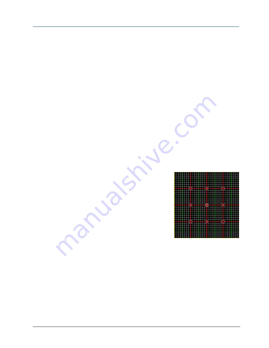
At this point, you should be viewing the two projected grids with
statistics displayed. If you do not see an output, check that all
Modifier parameters are set to their default values.
TIP: Before you begin other adjustments, physically view
the grid from along the centerline of the fixture. The centerline of the grid should
align with the center of the sphere. You can easily adjust any variation using the
Pan channel. The object is to align the vertical lines of the guide with the vertical
axis of the sphere.
Adjust output positioning on the sphere:
7. Use Global Effect Modifier 2 to adjust the latitude angle. You can view the Latitude top
and Latitude bottom statistics to see the degrees of or – from the “equator”.
8. Use Global Effect Modifiers 3 to move the output up or down to the part of the sphere
you want to cover. The Latitude top and Latitude bottom statistics show you the center of
adjustment in d or – from the “equator”.
9. Adjust the Global Effect Modifier 1 to set the longitude angle.
Summary of Contents for DL.3
Page 26: ...xxvi DL 3 Digital Light User Manual...
Page 32: ...CHAPTER 1 Product Overview 6 DL 3 Digital Light User Manual...
Page 72: ...CHAPTER 4 DMX Programming Basics and Quick Start 46 DL 3 Digital Light User Manual...
Page 83: ...CHAPTER 5 Tutorials DL 3 Digital Light User Manual 57...
Page 84: ...CHAPTER 5 Tutorials 58 DL 3 Digital Light User Manual...
Page 108: ...CHAPTER 8 Graphic Functions Rotation Position Scale 82 DL 3 Digital Light User Manual...
Page 140: ...CHAPTER 10 Graphic Functions Synchronizing Content 114 DL 3 Digital Light User Manual...
Page 160: ...CHAPTER 11 Global Functions 134 DL 3 Digital Light User Manual...
Page 172: ...CHAPTER 12 Global Functions Collage Generator Effect 146 DL 3 Digital Light User Manual...
Page 266: ...CHAPTER 13 Effect Mode Options Descriptions 240 DL 3 Digital Light User Manual...
Page 306: ...CHAPTER 16 Content Management Application CMA 280 DL 3 Digital Light User Manual...
Page 324: ...CHAPTER 16 Content Management Application CMA 298 DL 3 Digital Light User Manual...
Page 380: ...APPENDIX A DMX Protocol 354 DL 3 Digital Light User Manual...
Page 394: ...APPENDIX E Safety Information 368 DL 3 Digital Light User Manual...


