background image

4/18/11

888-2587-001

2-9

WARNING: Disconnect primary power prior to servicing.

Section 2 Installation & Initial Turn-On

FM HD Radio System

STEP 3

Turn on, then allow time for the exciter to boot up to normal operational 

mode - about 40 seconds for HD operation - and then verify there are no 
fault indications on any system device

NOTE:

Refer to the HDx-FM manual (888-2570-001) for detailed information pertaining 
to specific exciter functions.

STEP 4

Turn on any Circuit Breakers, On/Off or Power switches for other 

system devices

STEP 5

Observe all devices for fault indications

STEP 6

Verify the Harris Factory Test Data or similar documentation supplied 

with the equipment for typical readings

2.4.2

Bring Up Each Transmitter (Cabinet) Independently

It is recommended that each transmitter be initially connected directly to a test load and 
turned on, independently. Refer to corresponding documentation for detailed 
procedures to verify proper operation. 

2.4.3

Dual Cabinet Transmitter Systems

Once the correct operation of both transmitter cabinets of a Dual cabinet system 
(ZDHD+) is verified independently, they must be combined, amplitude and phase 
adjusted, and tested as a single entity. Refer to corresponding documentation for 
detailed procedures to perform alignments and verify proper operation. 

2.4.4

Connect All Transmitters to Combiner System

After the operation of each transmitter is verified, connect the combiner system 
according to the system design. 

2.4.5

SLC Phase Alignment

NOTE:

ZX transmitters are not configured for split level combining (SLC) per se. That 
is, they are not aligned in factory for the transmission of a non-standard FM to 
HD power ratio for use with a split level combiner. If SLC operation is desired 
with a ZX transmitter, please contact Harris for information on the necessary 
modifications and adjustments.

Summary of Contents for FlexStar

Page 1: ...FM HD Radio System T M No 888 2587 001 Copyright Harris Corporation 2006 2007 All rights reserved TECHNICAL MANUAL 888 2587 001 FM HD Radio System Rev C1 04 19 07...

Page 2: ...Locate and retain all PACKING CHECK LISTs Use the PACKING CHECK LIST to help locate and identify any components or assemblies which are removed for shipping and must be reinstalled Also remove any shi...

Page 3: ...11 888 2587 001 WARNING Disconnect primary power prior to servicing Manual Revision History FM HD Radio System REV DATE ECN Pages Affected Preliminary 2 03 2006 Created C 2 28 2007 P35719 Released MR...

Page 4: ...888 2587 001 4 18 11 WARNING Disconnect primary power prior to servicing MRH 2...

Page 5: ...TIONS column 1 gives the reference designators for the item i e C001 R102 etc that corresponds to the number found in the schematics C001 in a bill of material is equiva lent to C1 on the schematic or...

Page 6: ......

Page 7: ...is equipment local building codes and fire protection standards must be observed The following National Fire Protection Association NFPA standards are recommended as reference Automatic Fire Detectors...

Page 8: ...888 2587 001 4 18 11 WARNING Disconnect primary power prior to servicing WHILE IT IS HOT DUE TO THE POSSIBILITY OF A CASE RUPTURE AND SUBSE QUENT INJURY...

Page 9: ...ssible e If arms or legs are affected keep them elevated NOTE If medical help will not be available within an hour and the victim is conscious and not vomiting give him a weak solution of salt and sod...

Page 10: ...smission line o Site grounding configuration o Tools and craft skills to cut and assemble rigid line o Coordinate with electrician to connect AC service to transmitter o Any tower antenna work conside...

Page 11: ...to connect to an audio automation system for song title and artist name o Ethernet LAN integration with sub netting and routing Have you verified your current antenna system is working properly o Wide...

Page 12: ...888 2587 001 4 18 11 WARNING Disconnect primary power prior to servicing...

Page 13: ...Cabinet Interconnections 2 6 RF Sample for RTAC 2 6 Power Supply Connections 2 6 Circulator 2 6 Audio Connections 2 6 Ethernet Data Connections 2 7 Initial Turn On 2 8 General Startup Information 2 8...

Page 14: ...2 FAULT LED Illuminated 3 12 Section 4 Boost Pro Theory of Operation Introduction 4 1 Boost Pro Circuit Descriptions 4 1 Signal Descriptions 4 3 A to D Converter 4 4 Power Supplies 4 4 Front Panel 4 4...

Page 15: ...om the Exporter possibly through an STL is 300 kbps Ethernet for the digital carriers connected to the EXPORTER LINK input Enter in the Exporter link IP to match that on the Exporter screen The audio...

Page 16: ...in audio drop outs will result The Importer will manage the bandwidth allocated for each of the inputs for the digital carriers The Importer must be co located with the Exporter You will need a keyboa...

Page 17: ...Application Programmers Interface A set of programming commands used to manipulate an existing program Dual Input Antennas a low loss method of developing an FMHD hybrid signal Dual input antennas uti...

Page 18: ...gn Interleaved Antennas a low loss space combining method that employs two antenna inputs one for FM and a second for the HD signal In an interleaved antenna system the antenna bays are alternately ra...

Page 19: ...el Combining SLC A Harris exclusive method of developing a hybrid IBOC signal using a combination of separate amplification and common amplification Today s systems utilize a 3dB 4 77dB or 6dB hybrid...

Page 20: ...Other EOC components like the Connection Manager and the Logistics Processor write data about their functioning into the EOC Database The EOC Monitor component connects to the EOC database to view th...

Page 21: ...Operating modes for the HD carriers MP2 is 6 kHz wider toward outer of channel and MP3 14 kHz wider than MP1 MP4 328 kHz wider There is a corresponding increase in payload data rate Special permission...

Page 22: ...more of the following devices depending on the studio STL and site configuration HDI 100 Importer HDE 100 Exporter HDx FM Exciter These pieces of equipment will have a their own documentation possibly...

Page 23: ...d information regarding specifications installation operation maintenance theory and troubleshooting for each specific device 1 5 1 HDx FM Exciter Reliable DSP platform The HDx FM utilizes an embedded...

Page 24: ...m resistive device connected to the Reject Port of a high power combiner It must be appropriately sized and should be monitored at all times as it will be continuously utilized under the predicted nor...

Page 25: ...rol of a transmitter and facility 1 5 7 Power Monitoring Device A power averaging monitor device will be necessary to accurately measure and display the RF signal level With IBOC systems the more moni...

Page 26: ...d IPAs upon a malfunction Redundant RF amplifier modules that allow maintenance while the transmitter remains on the air at reduced power Hot Pluggable modules Redundant power supplies to keep the tra...

Page 27: ...f operation also known as Modulation Format that may be used in a typical IBOC system including a backup mode The four modes of operation are FM Analog RF only this could be the analog backup mode in...

Page 28: ...1 14 888 2587 001 4 18 11 WARNING Disconnect primary power prior to servicing FM HD Radio System Section 1 Introduction Specifications...

Page 29: ...which may have loosened during shipment Also check that all ribbon cables are properly locked into their respective printed circuit board connectors and that the all modules or boards are securely in...

Page 30: ...r prior to servicing FM HD Radio System Section 2 Installation Initial Turn On 2 2 4 Weight and Dimensions Where necessary refer to shipping containers and the corresponding documentation for the weig...

Page 31: ...4 18 11 888 2587 001 2 3 WARNING Disconnect primary power prior to servicing Section 2 Installation Initial Turn On FM HD Radio System Figure 2 1 Cable Layout...

Page 32: ...es of operation circuitry nomenclature and performance characteristics for each piece of system equipment to be installed The transmitter installation is accomplished in the following order 1 Equipmen...

Page 33: ...around the facility and lightning protection must be in place for any type of signal entering or leaving the facility This section is a brief introduction to grounding practices it is not intended to...

Page 34: ...dB pad to the RTAC RF Sample Input labeled XMTR on the HDx exciter rear panel In ZX transmitters an RF sample from the monitor port is divided by a 6 dB splitter to feed the station modulation monitor...

Page 35: ...Disconnect primary power prior to servicing Section 2 Installation Initial Turn On FM HD Radio System 2 3 9 Ethernet Data Connections All ethernet cables connected should be shielded twisted pair STP...

Page 36: ...e input INTERNAL and Exgine Output PATTERN It is very important to note that this HD Test Pattern mode must have Exgine input set to Exporter and Exgine output NORMAL for normal HD operation once the...

Page 37: ...to a test load and turned on independently Refer to corresponding documentation for detailed procedures to verify proper operation 2 4 3 Dual Cabinet Transmitter Systems Once the correct operation of...

Page 38: ...ss and hold for 2 seconds or more the LOWER button to instantly put the the ZHD power to zero STEP 5 Turn on the FM HD transmitter STEP 6 Carefully raise the power of the FM HD transmitter while obser...

Page 39: ...ize the lightning voltage potential carried by the coax into your building For multiple coax a single point of entry into the building is best with all connected to a common grounding plate or bulkhea...

Page 40: ...e automation equipment The interconnection for MPS PAD begins at the automation system equipment at the studio Audio Vault Prophet etc Typically it is over Ethernet and needs to connect to the Exporte...

Page 41: ...at the MAIN Delay OUT connector A 3 pin male XLR connector It goes to the FM processor for delivery to the HDx FM Exciter via an STL if not co located 2 6 4 4 44 1 kHz Clock OUT This output from the E...

Page 42: ...audio board Utilize the Exporter 44 1 kHz clock output for the sync in to the rate converter If the processor does not have a rate converter a separate rate converter will be needed or an audio input...

Page 43: ...essor rate converter prior to the Importer They will connect to the cable bundle on the rear of the Importer Other inputs are SPS PAD and any Advance Applications Services AAS that may be used via Eth...

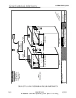
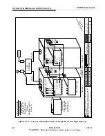
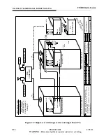
Page 44: ...some have subtle differences between them Locate the one that closely fits your situation In the lower right hand corner of each drawing are two configuration numbers The numbers refer to details used...

Page 45: ...O DISCLOSURE REPRODUCTION OR USE OF ANY PART THEREOF MAY BE MADE EXCEPT BY WRITTEN PERMISSION DATE ZONE LTR ENG ECO NBR DFTM S I V E R I O N FLEXSTAR EXCITER RTAC SAMPLE MUTE FAULT SAMPLE APC TX CNTRL...

Page 46: ...RIS CORPORATION NO DISCLOSURE REPRODUCTION OR USE OF ANY PART THEREOF MAY BE MADE EXCEPT BY WRITTEN PERMISSION DATE ZONE LTR ENG ECO NBR DFTM S E T O N S I V E R I O N FLEXSTAR EXCITER RTAC SAMPLE MUT...

Page 47: ...TA OF HARRIS CORPORATION NO DISCLOSURE REPRODUCTION OR USE OF ANY PART THEREOF MAY BE MADE EXCEPT BY WRITTEN PERMISSION DATE ZONE LTR ENG ECO NBR DFTM S E T O N S I V E R I O N FLEXSTAR EXCITER RTAC S...

Page 48: ...ION DATE ZONE LTR ENG ECO NBR DFTM S E T O N S I V E R I O N FLEXSTAR EXCITER RTAC SAMPLE AUX RF OUT MUTE FAULT SAMPLE APC TX CNTRL LOW LEVEL ZDHD CONFIGURATION Single Flexstar Single Boost Pro Excite...

Page 49: ...XSTAR EXCITER RTAC SAMPLE AUX RF OUT CAN BUS MUTE FAULT SAMPLE APC TX CNTRL F M H D R F O U T LOW LEVEL ZDHD CONFIGURATION Dual Flexstar Dual Boost Pro Exciters located in Cabinet A BOOST PRO RF IN MU...

Page 50: ...T SAMPLE APC TX CNTRL F M R F O U T LOW LEVEL ZDHD CONFIGURATION Single Flexstar Single Boost Pro Digit for Analog Backup Exciters located in Cabinet A BOOST PRO RF IN MUTE FAULT SAMPLE APC MODE Cabin...

Page 51: ...EOF MAY BE MADE EXCEPT BY WRITTEN PERMISSION DATE ZONE LTR ENG ECO NBR DFTM S E T O N S I V E R I O N ANALOG EXCITER ANALOG TRANSMITTER HIGH LEVEL ZHD CONFIGURATION Single Flexstar Exciter FLEXSTAR EX...

Page 52: ...STAR EXCITER RTAC SAMPLE AUX RF OUT MUTE FAULT SAMPLE APC TX CNTRL F M R F O U T ANALOG TRANSMITTER HIGH LEVEL ZHD CONFIGURATION Single Flexstar Single Boost Pro Exciter located in Analog Tx BOOST PRO...

Page 53: ...USE OF ANY PART THEREOF MAY BE MADE EXCEPT BY WRITTEN PERMISSION DATE ZONE LTR ENG ECO NBR DFTM S E T O N S I V E R I O N FLEXSTAR EXCITER RTAC SAMPLE MUTE FAULT SAMPLE APC TX CNTRL H D R F O U T HIGH...

Page 54: ...R HIGH LEVEL ZHD CONFIGURATION Dual Flexstar Single Boost Pro Exciters located in Analog Tx BOOST PRO RF IN MUTE FAULT SAMPLE APC MODE RF SAMPLE ZHD TRANSMITTER RF SAMPLE 10DB COMBINER LOAD METERING H...

Page 55: ...O N S I V E R I O N ANALOG TRANSMITTER HIGH LEVEL ZHD CONFIGURATION Dual Flexstar Dual Boost Pro Exciters located in Analog Tx BOOST PRO RF IN MUTE FAULT SAMPLE APC MODE RF SAMPLE ZHD TRANSMITTER RF S...

Page 56: ...ANALOG TRANSMITTER HIGH LEVEL ZHD CONFIGURATION Single Flexstar Single Boost Pro Digit for Analog Backup Exciters located in Analog Tx BOOST PRO RF IN MUTE FAULT SAMPLE APC MODE RF SAMPLE ZHD TRANSMIT...

Page 57: ...ECO NBR DFTM S E T O N S I V E R I O N HIGH LEVEL ZDHD CONFIGURATION Single Flexstar Exciter Single Boost Pro ANALOG EXCITER ANALOG TRANSMITTER FLEXSTAR EXCITER RTAC SAMPLE AUX RF OUT MUTE FAULT SAMP...

Page 58: ...TAR EXCITER RTAC SAMPLE AUX RF OUT MUTE FAULT SAMPLE APC TX CNTRL HIGH LEVEL ZDHD CONFIGURATION Single Flexstar Dual Boost Pro Exciter located in Analog Tx BOOST PRO RF IN MUTE FAULT SAMPLE APC MODE C...

Page 59: ...IGURATION Dual Flexstar Exciters Dual Boost Pro ANALOG EXCITER ANALOG TRANSMITTER FLEXSTAR EXCITER RTAC SAMPLE AUX RF OUT MUTE FAULT SAMPLE APC TX CNTRL H D R F O U T BOOST PRO RF IN MUTE FAULT SAMPLE...

Page 60: ...CNTRL F M R F O U T HIGH LEVEL ZDHD CONFIGURATION Dual Flexstar Dual Boost Pro Exciters located in Analog Tx BOOST PRO RF IN MUTE FAULT SAMPLE APC MODE Cabinet B RF SAMPLE 10DB COMBINER LOAD HD RF OU...

Page 61: ...LT SAMPLE APC TX CNTRL F M R F O U T HIGH LEVEL ZDHD CONFIGURATION Single Flexstar Dual Boost Pro Digit for Analog Backup Exciters located in Analog Tx BOOST PRO RF IN MUTE FAULT SAMPLE APC MODE Cabin...

Page 62: ...RTAC SAMPLE AUX RF OUT MUTE FAULT SAMPLE AFC TX CNTRL F M R F O U T ANALOG TRANSMITTER SPLIT LEVEL ZHD CONFIGURATION Single Flexstar Single Boost Pro Exciter located in Analog Tx BOOST PRO RF IN MUTE...

Page 63: ...ART THEREOF MAY BE MADE EXCEPT BY WRITTEN PERMISSION DATE ZONE LTR ENG ECO NBR DFTM S E T O N S I V E R I O N ANALOG TRANSMITTER SPLIT LEVEL ZHD CONFIGURATION Dual Flexstar Single Boost Pro Exciters l...

Page 64: ...V E R I O N ANALOG TRANSMITTER SPLIT LEVEL ZHD CONFIGURATION Dual Flexstar Dual Boost Pro Exciters located in Analog Tx BOOST PRO RF IN MUTE FAULT SAMPLE APC MODE RF SAMPLE ZHD TRANSMITTER RF SAMPLE 3...

Page 65: ...ANSMITTER SPLITLEVEL ZHD CONFIGURATION Single Flexstar Single Boost Pro Digit for Analog Backup Exciters located in Analog Tx BOOST PRO RF IN MUTE FAULT SAMPLE APC MODE RF SAMPLE ZHD TRANSMITTER RF SA...

Page 66: ...SAMPLE AUX RF OUT MUTE FAULT SAMPLE APC TX CNTRL SPLIT LEVEL ZDHD CONFIGURATION Single Flexstar Dual Boost Pro Exciter located in Analog Tx BOOST PRO RF IN MUTE FAULT SAMPLE APC MODE Cabinet B RF SAM...

Page 67: ...M R F O U T SPLIT LEVEL ZDHD CONFIGURATION Dual Flexstar Dual Boost Pro Exciters located in Analog Tx BOOST PRO RF IN MUTE FAULT SAMPLE APC MODE Cabinet B RF SAMPLE 3 4 77 or 6DB COMBINER LOAD FM HD R...

Page 68: ...E APC TX CNTRL F M R F O U T SPLIT LEVEL ZDHD CONFIGURATION Single Flexstar Dual Boost Pro Digit for Analog Backup Exciters located in Analog Tx BOOST PRO RF IN MUTE FAULT SAMPLE APC MODE Cabinet B RF...

Page 69: ...citers located in Two Analog TXs BOOST PRO RF IN MUTE FAULT SAMPLE APC MODE RF SAMPLE ZHD TRANSMITTER RF SAMPLE 3 4 77 or 6DB COMBINER LOAD METERING METERING FM HD RF OUTPUT FM RF OUTPUT FLEXSTAR EXCI...

Page 70: ...XLR to DB 25 Breakout Cable 44 1 kHz CLOCK OUT 110 OHM to 75 OHM IMPEDANCE TRANSFORMER CANARE P N BCJ XJ TRB HARRIS P N BCJ XJ TRB HDI 100 IMPORTER ETHERNET ETHERNET T1 SERVICE SPS1 AES AUDIO Custome...

Page 71: ...to 96kHz Customer Selected Equipment FM HD AUDIO PROCESSOR ETHERNET HDE 100 EXPORTER MPS AUDIO IN MAIN DELAY IN MAIN DELAY OUT 44 1 kHz CLOCK OUT AES OUT 2 AES IN AES OUT 1 HOST FM AES AUDIO AES ONLY...

Page 72: ...ted Equipment SPS1 AUDIO PROCESSOR RATE CONVERTER AES 1 IN AES 1 OUT AES 1 IN AES 1 OUT SPS2 AES AUDIO SPS1 AES AUDIO SYNC IN SYNC IN SPS2 AUDIO PROCESSOR RATE CONVERTER AES 1 IN IMPORTER AT TRANSMITT...

Page 73: ...EXCITER EXPORTER LINK COMPOSITE TX INTERFACE RTAC XMTR RF OUTPUT AUX RF OUT MAIN AES W148 RF SAMPLE TO TRANSMITTER SYSTEM CAN W903 CAN BUSS W123 UPPER REAR CABINET CONTROLLER DISPLAY BACKPLANE BOARD J...

Page 74: ...2 46 888 2587 001 4 18 11 WARNING Disconnect primary power prior to servicing FM HD Radio System Section 2 Installation Initial Turn On...

Page 75: ...ailed informa tion 3 2 ZHD Front Panel Functions and displays The Front Panel of the HDx FM exciter Boost Pro and the Platinum Z ZHD ZHD transmitter s are the primary operational status indications of...

Page 76: ...l change from a to the actual forward power in Watts If it is desired to change the RF output power press and hold the RAISE or LOWER button until level is reached For small changes momentarily press...

Page 77: ...on your equipment for further details and refer to the HELP screens on the unit for more information NOTE Refer to the specific technical manual of the FlexStar HDx FM Exciter for detailed informatio...

Page 78: ...dividual PA module accompa nied by red LED above PA module or in a combiner reject load otherwise EXTERNAL MUTE a forced MUTE condition typically caused by the user mute control or the exciter ready m...

Page 79: ...e transmitter or any abnormal conditions do not restrict the operation of the transmitter b Ensure the transmitter RF output is connected to the proper load or antenna c Check the User Interface panel...

Page 80: ...at all units are properly shut down STEP 1 Press OFF Power button on each transmitter STEP 2 If desired turn off ZHD rear upper sidewall circuit breaker STEP 3 If desired turn off any Circuit Breakers...

Page 81: ...9 9 9 9 9 9 9 5 67 786 087 67 786 67 087 8 7 675 2 2 2 2 087 32 67 087 32 3 02 6 5 9 5 9 2 7 3 96 5 75 3 3 5 75 3 3 7 03 3 855 2 2 2 2 3 29 5 9 3 81 5 9 1 7 3 81 2 9 2 2 2 2 2 9 2 9 2 9 2 9 2 9 2 9 2...

Page 82: ...ecific technical manual of the system device malfunctioning for detailed information 3 6 1 General System Response Depending on the Front Panel indications early steps in troubleshooting a transmitter...

Page 83: ...r the fault description in the Diagnostic Display s fault log If more troubleshooting is necessary a technician can refer to Section 6 of that manual for fault explanations 3 6 3 2 FOLDBACK LED Illumi...

Page 84: ...ult description in the Diagnostic Display s fault log If more troubleshooting is necessary qualified personnel can refer to Section 6 of that manual for fault explanations 3 6 4 ZX Emergency Response...

Page 85: ...arty remote control product 3 6 4 2 ZX First Response Troubleshooting If the transmitter output power is low or zero perform the following checks 1 Are the PS module fans running with a green AC OK li...

Page 86: ...ion is detected Press INFO then FAULT SUBMENU to view a listing of statuses where the malfunction would be indicated by the word FAULT Refer to 6 2 1 Boost Pro Fault Indication on page 6 2 To reset th...

Page 87: ...hanged by adjusting the voltage on a variable attenuator in line with the RF signal The source of the APC voltage can be switched between an external source via the transmitter interface connector or...

Page 88: ...4 2 888 2587 001 4 18 11 WARNING Disconnect primary power prior to servicing FM HD Radio System Section 4 Boost Pro Theory of Figure 4 1 Boost Pro Block Diagram...

Page 89: ...control the phase of the RF signal RFLD_PWR_TRIP This voltage will set a trip point to mute the PA if the reflected power becomes too great This voltage will change when the modulation mode changes FW...

Page 90: ...supply at 5Vdc 15Vdc and 15Vdc Both power supplies are capable of 85 264VAC 47 440Hz inputs 4 2 4 Front Panel The front panel uses a 128x64 dot LCD warning LEDs and buttons to interact with the Boost...

Page 91: ...SLC systems should periodically be checked for best lowest reject power If the reject power has increased verify the power out of each transmitter the SLC FM HD carrier levels and possibly readjust t...

Page 92: ...Pro s status submenu CAN COMM should read OK 5 5 AC surge protection Input AC surge suppression and grounding configuration integrity should be checked at the beginning of the lightning season 5 6 So...

Page 93: ...n page 3 8 for initial steps in restoring a transmitter to operational status in the event of a fault condition The first step will be to attempt to determine which unit is causing the malfunction by...

Page 94: ...el LED will turn red if a fault condition is detected Press INFO then FAULT SUBMENU to view a listing of statuses where the malfunction would be indicated by the word FAULT To reset the fault press IN...

Page 95: ...e ALC reference is greater than 50 counts lasting for more than 2 5 seconds Fault off 24V 15V 12V 15V 12V 8V 5V 3V Low Voltage Power Supplies All on board low voltage supplies thresholds are 20 Warnin...

Page 96: ...A square block ending point of a named signal accompa nied by a number forward slash letter number is an indication of that signal continu ing on to another page of schematic Example AUDIO 14 D1 Indic...

Page 97: ...eps necessary to physically connect start the terminal program electronically handshake with navigate the VT100 screens and perform edits STEP 1 Turn transmitter off STEP 2 Connect RS 232 comm port 2...

Page 98: ...s Page 4 of the VT100 programming From page 3 press and hold your keyboard s Shift key then press 1 then press 2 and then press 3 From that point on during this session you will have access to this pa...

Page 99: ...Mute condition for the Boost Pro when OFF the Boost Pro is not muting the signal Fault Strike Status OK FAIL Status of the fault strike condition when OK the Boost Pro has not entered or completed a...

Page 100: ...to factory presets f Fault Reset Typing f will reset the Fault Strike Status t Build in Test IO FACTORY USE ONLY This is a test run in the factory to make sure all the communications are working corr...

Page 101: ...to STAND ALONE TX This is the only condition where the TX Type STAND ALONE TX is available 4 Mute Polarity ACTIVE LOW ACTIVE HIGH DISABLED 5 Fast Mute Polarity ACTIVE LOW ACTIVE HIGH DISABLED 6 Power...

Page 102: ...ND OR ANY DOWNSTREAM EQUIPMENT TRANSMITTERS COMBINERS REJECT LOADS ANTENNAS ETC FAULTS The faults listed on the right side of the screen are self explanatory with the exception of A BIT fail and D BIT...

Page 103: ...l to Analog Converters The information on the left side of the screen is data coming from an external analog to digital converter The internal analog to digital converter is being used to sample the v...

Page 104: ...6 12 888 2587 001 4 18 11 WARNING Disconnect primary power prior to servicing FM HD Radio System Section 6 Troubleshooting...

Page 105: ...y important to note that this HD Test Pattern mode must be DISABLED for normal HD operation once the HDE 100 is properly connected and configured NOTE Prior to connecting both the HDx FM exciter and H...

Page 106: ...6 14 888 2587 001 4 18 11 WARNING Disconnect primary power prior to servicing FM HD Radio System Section 6 Troubleshooting...

Reviews: