4/18/11
888-2587-001
4-1
WARNING: Disconnect primary power prior to servicing.
Section 4
Boost Pro Theory
of Operation
4
4.1
Introduction
This section of the manual provides circuit descriptions for the Boost Pro boost
amplifier.
4.2
Boost Pro Circuit Descriptions
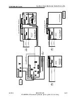
Refer to Figure 4-1 on page 4-2 for the following descriptions. The Boost Pro boost
amplifier can be divided into three parts for sake of circuit discussion: Control,
amplification, and display. The control portion handles the communication, phase
adjustment, and the power control of the RF signal. Amplification applies a gain of
+45dB to the RF signal. Finally, the display interfaces with the control via SPI bus. The
same amplifier used in the FlexStar™ Exciter is used in the Boost Amplifier.
The Controller monitors the power amplifier and relays information to the various
connectors. Output power level can be changed by adjusting the voltage on a variable
attenuator in line with the RF signal. The source of the APC voltage can be switched
between an external source via the transmitter interface connector, or an internal digital-
to-analog converter. This APC switch is controlled by the microcontroller. The phase of
the RF can also be adjusted via the microcontroller, or by information entering on the
RS232 port, GUI, or CAN interfaces. Communication and internal decision making is
done by the ‘376 Micro Module, which is a 32-bit microcontroller (MC9S12DP256)
with 256k of flash memory and 256k of SRAM memory. A CPLD (complex
programmable logic device - XC9536) is used to add logic to the monitoring of the
power amplifier and to add gating logic to the LCD display.
The automatic power control (APC) voltage of the system is selectable from two
different sources, external or internal. The APC signal controls the DC bias on a
variable attenuator in-line with the RF path feeding the power amplifier. The purpose of
the APC is to keep the power of the transmitter at a constant power level.

