Harmonic ELECTRA VS User Manual Download Page 287

Chapter 3 ’Web User Graphical Interface’ — Workflow Library

Electra VS - Version 05.10 

287

User Manual - Rev. A

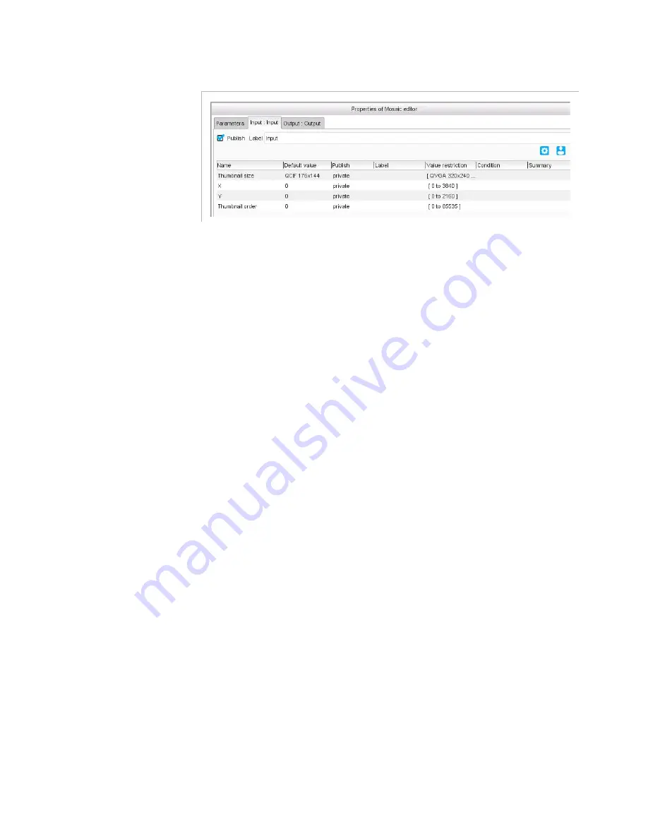
Figure 3-258.  Mosaic editor specific parameters

Link inputs to add thumbnails to your mosaic. For each linked input, you 
must also set the following specific parameters:

Thumbnail size

: size to which the input will be resized. Choose a 

format from the list or choose 

Custom

 and specify your values in the 

Custom thumbnail size 

field.

X

 and 

Y

: position of the upper left corner of the thumbnail, relative to 

the upper left corner of the background.

Thumbnail order

: order used if a thumbnail partially covers another 

one, to know which thumbnail should be on top of the other, 0 being 
in front of 1, etc. Make sure you do not use twice the same value as 
the overlap would then be random.

Summary of Contents for ELECTRA VS

Page 1: ...Rev A ELECTRA VS Convergent Video System Version 05 10 User Manual...

Page 2: ...Copyright 2017 Harmonic Inc All rights reserved...

Page 3: ...lation and Startup 31 Hardware Delivery 32 Chassis Overview 32 Front Panel 33 Rear Panel 35 HP Documentation 38 Unpacking 40 Mounting in Rack Recommendations 40 Ventilation 40 Cabling 40 Power Supply...

Page 4: ...se for Electra VS 67 Declaring a License for Electra VS 67 Adding Non Masterisable Node s to Electra VS 68 Defining Processing Capacity of the Nodes 68 Finalizing Network Configuration 68 Starting the...

Page 5: ...anced Operations 117 Creating an MPTS Job 117 Creating an MPTS Job with Statmux 121 Creating your Own Workflows 125 Creating a Workflow from Scratch 125 Adapting a Sample Workflow 137 Creating Sub Wor...

Page 6: ...Tab 190 Left Area 190 Buttons 190 Search 191 List 191 Description 193 Right Area 193 Buttons 193 Copy and Paste Options 194 Workflow Import and Export Options 195 Categories and Colors 196 Jobs Tab 19...

Page 7: ...ut and Output Parameters 234 Multi Instance 235 Processing Component Common Parameters 236 Conditioned Parameters Display Button 236 Publication Mode Switch Button 236 Link Tool 236 Processing Compone...

Page 8: ...g 356 Smooth Streaming File Output 363 MPEG DASH 366 MPEG DASH File Output 374 MP4 File Output 378 Selector and Choice Tools 380 Dialog Description 380 Parameter 380 Conditions 380 Choice 380 Selector...

Page 9: ...Simple Movie Contents 404 Recommended H 265 Settings in Live UHD 406 Chapter 4 Servicing 407 Common 408 Managing the Recovery Points 408 Overview 408 Recovery Points Management 408 Upgrading the Soft...

Page 10: ...pgrading the Software Release 444 Requesting a New License File 444 Declaring a New License File 444 Adding a Masterisable Node to Electra VS 444 Adding a Slave Node to Electra VS 445 Replacing a Mast...

Page 11: ...ching VOS Flex NodeBench on New Hardware Resource 466 Using VOS Flex NodeBench 467 Equipment Setup 469 Overview 469 Operation 469 Launching Equipment Setup 469 Connecting to a Device 470 Setting Devic...

Page 12: ...504 Electra VS 1RU AC 100 240V single phase 504 Blade Center Physical Interface Specifications 505 HP 1RU Hardware available Configurations 506 Software Only Requirements Specifications 512 Virtualiza...

Page 13: ...Categories 564 List of Logs 565 Appendix F Network Settings 573 Hardware Delivery 6RU and 10RU devices 574 Blades 574 Internal Switches Flex10 574 Interface Bonding 574 10RU Device 574 6RU Device 575...

Page 14: ...82 Software Only Delivery 583 Virtualization Delivery 583 Appendix G ESAM 585 ESAM Implementation 586 Appendix H Aspect Ratio Conversions 587 Conversions according to input AFD and output display aspe...

Page 15: ...cing your basic knowledge of the product The Electra VS Quick Start Guide contains information about installing and configuring the equipment The Electra VS Web Services SOAP API documentation provide...

Page 16: ...ion on how to return a product Chapter 7 Tools describes the Equipment Setup tool delivered on the DVD ROM with the product It describes also the NodeBench tool Appendix A Technical Specifications giv...

Page 17: ...Electra VS is implementing the API Signal Confirmation and Conditioning for CableLabs ESAM Event Signaling and Management Appendix H Aspect Ratio Conversions provides the default conversion performed...

Page 18: ...re this product is operated Follow Instructions All operating and use instructions should be followed Terms in this Manual Safety related statements appear in this manual in the following form Warning...

Page 19: ...are instructed to select click or clear Example Select Settings from the Configuration menu Blue text refers to document names sections figures or tables Example Refer to Section Warnings Cautions and...

Page 20: ...y a right under any patent or any other industrial or intellectual property right of Dolby Laboratories to use this Implementation in any finished end user or ready to use final product It is hereby n...

Page 21: ...er 1 Overview Introduction This chapter gives a general description of the Electra VS and its main features In this Chapter Purpose page 22 Main Features page 24 Hardware Delivery page 25 Software Onl...

Page 22: ...ly With built in 10GigE switches racking and cabling nightmares vanish Reliability built around highly resilient IT platforms equipped with hot swappable redundant components the Electra VS provides n...

Page 23: ...Chapter 1 Overview Purpose Electra VS Version 05 10 23 User Manual Rev A Figure 1 1 Electra VS applications Electra VS 1RU Electra VS 10RU...

Page 24: ...r channel Scalable number of input channels Scalable number of output profiles Advanced video and audio pre processing Integrated content protection HTTP Centralized Operation Workflow Builder SOAP We...

Page 25: ...ut no more available with Electra VS These chassis 6RU chassis G7 G8 1RU chassis are still described in this manual but not available for sale Physical characteristics are as follows Hot swappable pow...

Page 26: ...Version 05 10 User Manual Rev A 6RU Front Panel Figure 1 3 Electra VS 6RU server front panel 10RU Front Panel Figure 1 4 Electra VS 10RU server front panel Rear Panel 1RU Rear Panel Figure 1 5 Electr...

Page 27: ...ectra VS Version 05 10 27 User Manual Rev A Figure 1 6 Electra VS G8 1RU server rear panel Figure 1 7 Electra VS G9 1RU server rear panel 6RU Rear Panel Figure 1 8 Electra VS 6RU server rear panel slo...

Page 28: ...Chapter 1 Overview Hardware Delivery 28 Electra VS Version 05 10 User Manual Rev A 10RU Rear Panel Figure 1 9 Electra VS 10RU server rear panel...

Page 29: ...raging Harmonic s dedicated Video Operating System VOS Flex It operates on off the shelf IT servers For operators owning their servers Electra VS is available as Electra VS Software Edition More infor...

Page 30: ...or operators owning virtualization infrastructure Electra VS is available as Electra VS Virtualized Edition Virtualization Technologies Electra VS Virtualized edition can be delivered as a virtual mac...

Page 31: ...es of delivery It also contains a list of HP documents to which you can refer for more information on the blade centers In this Chapter Hardware Delivery page 32 Software Only Delivery page 57 Virtual...

Page 32: ...airflow For more information on the specifications refer to Appendix A Technical Specifications on page 481 The sections below show the front and rear panels of the devices For a full description of...

Page 33: ...and Startup Hardware Delivery Electra VS Version 05 10 33 User Manual Rev A Front Panel Figure 2 1 Electra VS 10RU server front panel Figure 2 2 Electra VS 6RU server front panel Figure 2 3 Electra VS...

Page 34: ...tem is serviceable without removing the server hood as in the case of a redundant power supply failure the External Health LED will illuminate If the item is serviceable by removing the hood as in the...

Page 35: ...p Hardware Delivery Electra VS Version 05 10 35 User Manual Rev A Rear Panel Figure 2 5 Electra VS 10RU server rear panel Figure 2 6 Electra VS 6RU server rear panel Figure 2 7 Electra VS G7 1RU serve...

Page 36: ...U server rear panel Figure 2 9 Electra VS G9 1RU server rear panel Depending on the server the content of the slots may vary On a G7 server Slot 0 4 Ethernet interfaces Slot 1 optional additional Ethe...

Page 37: ...board D network or E SDI VGA output Serial COM port Network connectors 4 to 1 iLO port Power supply connectors Optional redundant power supply unit Optional SDI board A B or C USB ports not used Othe...

Page 38: ...P Documentation HP provides a number of documents for their blade centers These documents are available on the HP Web site but you can also find them on the DVD ROM delivered with the Electra VS HP Bl...

Page 39: ...Connect Manager Command Line Interface for c Class BladeSystem User Guide HP BladeSystem c3000 Enclosure Quick Specs HP BladeSystem c7000 Enclosure Quick Specs HP Proliant BL460c G7 Quick Specs HP Pr...

Page 40: ...Cabling It is essential to separate the power supply cables from the signal cables When facing the rear of the rack as the device is connected via the rear panel the power supply cables must be guided...

Page 41: ...ld comply with the legislation in force in the country of installation The connection panel must be positioned in the rack in such a way that the plug and power cord s are within easy reach for switch...

Page 42: ...ts initial configuration 1RU Device 1 Mount the device in a rack 2 If not already installed mount the front panel shipped with the server a Engage the right side of the front panel in the notches of t...

Page 43: ...The procedure is not the same for 10RU and 6RU devices Mounting the Front Panel on 10RU Device The following items are shipped with the device 1 front panel left or right opening in a plastic bag 1 to...

Page 44: ...llows Position the top left hinge so that its top screw inserts into the hole in the top part of the front panel Figure 2 17 Inserting the top left hinge in the top part of the front panel Raise the f...

Page 45: ...dure to Install a Right Opening Front Panel Hinges on Right Figure 2 20 Front panel with right opening 1 Remove the top right hinge as shown in Figure 2 23 this time with the right hinge Left side pan...

Page 46: ...nge and front panel together on the chassis as shown in Figure 2 26 this time with the top right hinge Mounting the Front Panel on 6RU Device The following items are shipped with the device 1 front pa...

Page 47: ...nt panel with left opening 1 Remove the left hinge from the chassis see below Figure 2 23 Removing the left hinge 2 Install the front panel in the left hinge as follows Position the left hinge so that...

Page 48: ...he hinge to insert it in the bottom part of the front panel 3 Re mount the left hinge and front panel together on the chassis Figure 2 26 Fixing the left hinge Procedure to Install a Right Opening Fro...

Page 49: ...e top and bottom screws from the left hinge to the right hinge 3 Install the front panel in the right hinge as shown in Figure 2 24 and Figure 2 25 this time with the right hinge 4 Re mount the right...

Page 50: ...h Summary from the menu 3 Check that all indicators are green Performing the Initial Settings Preparing the Connection 1 Connect the system private LAN of all the platforms composing the Electra VS to...

Page 51: ...68 250 9 IP address which might happen if the factory set IP address has been modified use the Discover feature of the equipment set up tool See Chapter 7 Tools on page 465 Checking Node Status 1 Sele...

Page 52: ...on Set the following parameters Address Mask Gateway optional First address first address of the n consecutive addresses Supervision address 4 Set the Data 1 X3 on 6RU and 10RU devices network on the...

Page 53: ...n one unique switch or on two switches if they are redunded For 1RU devices a Disconnect NIC 1 from the GigE switch b Depending on the hardware configuration 1RU including two SD SDI octo boards Conne...

Page 54: ...et it from one PTP Grandmaster clock server add the LAN number and the Domain number of the server 4 Choose the time zone to use from the drop down list 5 Indicate if you want to adjust the time autom...

Page 55: ...TPS only and you are currently in HTTP you will have to stop the connection and restart a new one 2 If HTTPS only is activated the webTV outputs with get mode will not work on the corresponding networ...

Page 56: ...Installation and Startup Hardware Delivery 56 Electra VS Version 05 10 User Manual Rev A Starting the Operation Refer to Chapter Web User Graphical Interface section Operating Instructions Tutorial o...

Page 57: ...l configuration Preparing your Network Architecture Read all the recommendations related to the network in the IP architecture document delivered with the product in the DVD ROM directory Documentatio...

Page 58: ...image to USB Flash Drive for example imageUSB http www osforensics com tools write usb images html 2 Plug the USB Flash drive in the PC 3 Copy the installation image from the DVD ROM Software only De...

Page 59: ...ng method Depending on the hardware configuration If you have installed an Hardware RAID select Use one entire disk Hardware RAID or single disk or if you have installed two independent disks select U...

Page 60: ...p Software Only Delivery 60 Electra VS Version 05 10 User Manual Rev A c Finish the partitioning Select Finish partitioning and write changes to disk Press Enter d Select Yes and press Enter The insta...

Page 61: ...ollowing commands loadkeys fr us load the keyboard translation table if required setSystemIP declare the node as master node It may be used to configure the interface of the platform to be in the Syst...

Page 62: ...rier 0 collisions 0 txqueuelen 1000 RX bytes 40444 39 4 KiB TX bytes 141000 137 6 KiB eth1 Link encap Ethernet HWaddr bc 30 5b e4 fa 5e inet addr 198 18 69 244 Bcast 198 18 71 255 Mask 255 255 248 0 i...

Page 63: ...ect to the Electra VS Use the following account information Login admin If you cannot access to the management IP address previously configured Try to connect the PC to one of the others interfaces of...

Page 64: ...a VS Version 05 10 User Manual Rev A Password admin 4 Read and accept the End User License Agreement EULA The End User License Agreement shall be accepted only the first time the Web interface is open...

Page 65: ...de tab in the GUI The state of the first node shall be Slave its status OK and the processing capacity set to 0 The node shall be in integration mode check its status in the bottom right corner of the...

Page 66: ...he first node a Select the Hardware tab b Go to the Nodes category c Select Add Nodes The second node should be detected and displayed in the list If it is not the case check the interface configurati...

Page 67: ...sed Refer to Chapter 4 Servicing section Requesting a new license File on page 411 Declaring a License for Electra VS 1 Import the license generated by Harmonic Refer to Chapter 4 Servicing section De...

Page 68: ...al hardware platform exactly the same hardware and exactly the same configuration of the BIOS parameters import it on each node Otherwise launch a NodeBench analyze to measure the performances of the...

Page 69: ...he steps below to install the Electra VS and perform its initial configuration Read all the recommendations related to the network in the IP architecture document delivered with the product in the DVD...

Page 70: ...a different physical adapter At Virtual machine level associate each physical interface to one VMPG needed in the Electra VS For example Network adapter 2 used for Electra VS Management LAN will be e...

Page 71: ...d Startup Virtualization Delivery Electra VS Version 05 10 71 User Manual Rev A System private VMPG is mandatory even if you have only one node But in this case there is no need to associate this VMPG...

Page 72: ...Node Master Node 1 Copy the OVA image from the Virtualization Delivery directory to the PC 2 During the deployment of the OVA image associate the networks of the VM and the ones of the ESXi When the...

Page 73: ...l RAM Otherwise you may have an error when you start the Virtual machine 5 Select CPU a Configure the Number of virtual sockets to correspond to the real number of processors in your server b Configur...

Page 74: ...eck the Network adapter mapping At Virtual machine level we have associated one physical interface to one VMPG For example Network adapter 2 Management VS will be eth1 in Electra VS OS layer and NIC2...

Page 75: ...a autosize true sched cpu latencySensitivity high Configuring the Interface of the First Node Master Node Configure the first interface of the master node to be in the System Private LAN and set the I...

Page 76: ...nt network Accessing the Web interface for the First Time Refer to section Accessing the Web Interface for the First Time on page 63 Adding the Second Node in Electra VS Masterisable Node Add the seco...

Page 77: ...ion delivered in the DVD ROM with the product Finalize the network configuration by 1 Setting a Master node virtual IP address to the management LAN and use the Master node virtual IP address to conne...

Page 78: ...Chapter 2 Installation and Startup Virtualization Delivery 78 Electra VS Version 05 10 User Manual Rev A...

Page 79: ...hapter explains the Workflows and Jobs concept then describes how to use the Web Graphical User Interface to configure the equipment In this Chapter Workflows and Jobs Concept page 80 Operating Instru...

Page 80: ...ing from content acquisition to encoding and streaming and Jobs implementation of a given Workflow on a specific signal This permits to match any customer specific use case in a very easy way by creat...

Page 81: ...Electra VS Convergent Video System allows Logo addition in the video Text addition in the video Black Out Management Automatic Loudness Control on audio Content Protection Internal statistical multipl...

Page 82: ...ected for parameters that should be visible but not be changed when launching a job Public for parameters that should be visible and changed when launching a job Figure 3 3 Public Private and Protecte...

Page 83: ...do not fully match your requirements you may build your own workflows from sample workflows delivered in the DVD ROM This expert mode lets you expand the Electra VS capabilities considerably It is rec...

Page 84: ...flow by setting the public parameters The operator can launch as many jobs as needed based on this workflow As example when launching 20 OTT channels the operator will just have to launch 20 jobs base...

Page 85: ...pter 3 Web User Graphical Interface Workflows and Jobs Concept Electra VS Version 05 10 85 User Manual Rev A Subtitle Audio 1 Video Profile 3 Video Profile 4 Video Profile 1 Video Profile 2 Video Comm...

Page 86: ...meters to be changed can be limited to the inputs and outputs only It makes the product configuration flexible easy and quick After the few minutes required to launch the jobs they are all visible in...

Page 87: ...Overview Reaching the GUI Using the GUI Basic Operations Creating a Job from predefined workflows Setting Job parameters for predefined workflows Using the Snapshot view Advanced Operations Creating...

Page 88: ...quirements specified in Chapter Installation The Graphical User Interface GUI is a Java applet To launch it 1 Open a Web browser 2 Type the equipment IP address in the address bar and press Enter A we...

Page 89: ...r bar that provides information on the equipment status the date and time etc A Main area from where you can perform configuration and monitoring This area contains several tabs Click them to navigate...

Page 90: ...played In decreasing order the arrow is shown Moving and Docking Each view can be moved by dragging and dropping its title bar You can also move a view to drag the view over the left right top or bott...

Page 91: ...button To modify a value in a table double click the corresponding cell and type the new value or if it is a list select a value from the list In some lists it is also possible to add values For insta...

Page 92: ...Transcoder to be used for Live transcoding to an SPTS or MPTS statmux included output Table 3 3 Basic settings sub sections Sub section Description Creating a Job from a predefined workflow describes...

Page 93: ...ebTV with or without packaging Figure 3 13 Favorite workflows Later it will be possible for you to add your own favorite workflows in this list 3 Choose a workflow according to the target application...

Page 94: ...t priority The other jobs will be processed more slowly Speed if set to 1 the job will last at most as long as the video duration If set to 2 the job will last at most half as long as the video durati...

Page 95: ...e job monitoring panels Parameters Logs Nodes Snapshot Figure 3 17 Information on job The Parameters panel allows you to show edit the job parameters The Logs panel gives the alarms and events related...

Page 96: ...Workflows This section presents the parameter tabs of jobs based on the predefined workflows delivered with the product If you need details on the parameters refer to section Workflow Library on page...

Page 97: ...Chapter 3 Web User Graphical Interface Operating Instructions Tutorial Electra VS Version 05 10 97 User Manual Rev A Figure 3 21 Live SD HD Encoder job Video parameters...

Page 98: ...Web User Graphical Interface Operating Instructions Tutorial 98 Electra VS Version 05 10 User Manual Rev A Figure 3 22 Live SD HD Encoder job PIP parameters Figure 3 23 Live SD HD Encoder job Audio p...

Page 99: ...Chapter 3 Web User Graphical Interface Operating Instructions Tutorial Electra VS Version 05 10 99 User Manual Rev A Figure 3 24 Live SD HD Encoder job Audio1 parameters...

Page 100: ...User Graphical Interface Operating Instructions Tutorial 100 Electra VS Version 05 10 User Manual Rev A Figure 3 25 Live SD HD Encoder job Output parameters If Output TS type is SPTS in the Global Pa...

Page 101: ...ting Instructions Tutorial Electra VS Version 05 10 101 User Manual Rev A Live SD HD Transcoder Figure 3 26 Live SD HD Transcoder job Figure 3 27 Live SD HD Transcoder job Global parameters If Output...

Page 102: ...User Graphical Interface Operating Instructions Tutorial 102 Electra VS Version 05 10 User Manual Rev A Figure 3 28 Live SD HD Transcoder job Input parameters Figure 3 29 Live SD HD Transcoder job Vid...

Page 103: ...Graphical Interface Operating Instructions Tutorial Electra VS Version 05 10 103 User Manual Rev A Figure 3 30 Live SD HD Transcoder job PIP parameters Figure 3 31 Live SD HD Transcoder job Audio tran...

Page 104: ...nstructions Tutorial 104 Electra VS Version 05 10 User Manual Rev A Figure 3 32 Live SD HD Transcoder job Pass through component parameters Figure 3 33 Live SD HD Transcoder job Output parameters If O...

Page 105: ...Chapter 3 Web User Graphical Interface Operating Instructions Tutorial Electra VS Version 05 10 105 User Manual Rev A If Output TS type is MPTS in the Global Parameters tab...

Page 106: ...Graphical Interface Operating Instructions Tutorial 106 Electra VS Version 05 10 User Manual Rev A Live Web TV Transcoder Figure 3 34 Live Web TV Transcoder job Figure 3 35 Live Web TV Transcoder job...

Page 107: ...r 3 Web User Graphical Interface Operating Instructions Tutorial Electra VS Version 05 10 107 User Manual Rev A Figure 3 36 Live Web TV Transcoder job Input Figure 3 37 Live Web TV Transcoder job HLS...

Page 108: ...ting Instructions Tutorial 108 Electra VS Version 05 10 User Manual Rev A Figure 3 38 Live Web TV Transcoder job MPEG DASH output Figure 3 39 Live Web TV Transcoder job RTMP output Figure 3 40 Live We...

Page 109: ...ser Graphical Interface Operating Instructions Tutorial Electra VS Version 05 10 109 User Manual Rev A Figure 3 41 Live Web TV Transcoder job TS output Figure 3 42 Live Web TV Transcoder job Video com...

Page 110: ...Chapter 3 Web User Graphical Interface Operating Instructions Tutorial 110 Electra VS Version 05 10 User Manual Rev A Figure 3 43 Live Web TV Transcoder job Video profile 1 2...

Page 111: ...ser Graphical Interface Operating Instructions Tutorial Electra VS Version 05 10 111 User Manual Rev A Figure 3 44 Live Web TV Transcoder job Audio component Figure 3 45 Live Web TV Transcoder job Sub...

Page 112: ...ng the Workflow Create the workflow that you wish to apply on the files that will be placed on the hot folder For instance use the workflow procedure given in section Example Encoding a File on page 1...

Page 113: ...ce Operating Instructions Tutorial Electra VS Version 05 10 113 User Manual Rev A Using the Hot Folder Place a file in the input folder A job is automatically created to process the file and an output...

Page 114: ...nput Figure 3 48 Creating a new snapshot view for a TS over IP input a If your input is multicast check the corresponding box and set the LAN b Enter the destination IP address and UDP port of the TS...

Page 115: ...ode input network The entered value can be higher than the actual bitrate e g 40 Mbps for 38 Mbps actual rate If the entered value is lower than the actual bitrate a congestion is likely to occur on t...

Page 116: ...Version 05 10 User Manual Rev A Figure 3 50 Snapshot view _ Buttons and input content as a tree You can freeze the snapshot with the button To delete the snapshot you can either click the cross button...

Page 117: ...m scratch or by adapting an existing workflow how to create sub workflows how to create workflows with multi instantiable processing components Creating an MPTS Job To create an MPTS the following met...

Page 118: ...arameters for Input Video PIP Audio transcoding Pass trough component and Output Attention should be given to the following points set the Output TS type to MPTS in the Global parameters Figure 3 53 U...

Page 119: ...and UM_MPTS_CBR jobs parameter 2 Click to create a new MPTS and configure it with UM_MPTS_CBR as name 3 Click Create and start at the bottom of the dialog box to launch the multiplexing job UM_MPTS_CB...

Page 120: ...b Do not forget to choose the same MPTS name for each job here UM_MPTS_CBR since all jobs must share a same MPTS name to belong to the same MPTS Each program as well as the multiplexing are processed...

Page 121: ...program of the MPTS you wish to create The procedure is the same as previously except that you must set the Rate mode to Statmux and set the Minimum bitrate Maximum bitrate and Quality parameters in t...

Page 122: ...actually created one for the MPTS multiplexing process and one for the encoding process When creating the next jobs only the encoding job is created and it is linked to the MPTS multiplexing job crea...

Page 123: ...of the video component Minimum bitrate of the video component in bits per second Maximum bitrate of the video component in bits per second Quality of the video component in percentage set 90 for the m...

Page 124: ...Interface Operating Instructions Tutorial 124 Electra VS Version 05 10 User Manual Rev A Click Edit in the top right corner of the tab and change the parameters at your convenience if required Figure...

Page 125: ...will be followed by an example by adapting a sample workflow Creating a Workflow from Scratch If the predefined workflows do not fully match your requirements you may build your own workflows This ex...

Page 126: ...flow 3 Enter a name for your workflow 4 Assign a category Categories are used by Electra VS to classify the workflows this will be useful later to find a workflow more easily A number of categories ar...

Page 127: ...ur workflow This optional information can be edited or changed after workflow creation 6 Click OK Adding Processing Components to the Workflow Once the workflow is created you need to fill it with pro...

Page 128: ...se a processing component from the proposed list The option you are pointing with the mouse pointer is highlighted in the list and its description is displayed Figure 3 66 Linking to a new processing...

Page 129: ...ters are set to private Set the parameters that should be editable to public 4 From the default value column click the cells to add your values if needed This column displays the actual value when the...

Page 130: ...re not sorted Now hereunder the job panel based on the same workflow where parameters are sorted You can note that the parameters are now regrouped in more than one section with several groups in each...

Page 131: ...to create a new section b Click Rename to give it a proper name c Repeat these two operations for all the sections to create d Adjust the sections sequencing by moving up or down the sections Up or D...

Page 132: ...is created It appears underneath the list of parameters Figure 3 75 New group of parameters b Click the Rename button and give it a proper name 4 From the list of parameters select a parameter and dr...

Page 133: ...l Rev A Figure 3 77 Moving multiple parameters to a group Repeat these steps as many times as needed to sort all your parameters for instance as shown in Figure 3 78 below Figure 3 78 Parameters sorte...

Page 134: ...em is located 2 Click Check again Saving the Workflow Click Save The configuration is implicitly checked prior to saving Figure 3 80 Save button Example Encoding a File This section provides you with...

Page 135: ...er 1 TS audio packetizer 1 TS multiplexer 1 TS file output Prerequisite before creating the workflow make sure you have created the network storage s that will be used to read the input files and writ...

Page 136: ...o Any H 264 AVC encoder Bitrate Set to public label Output video bitrate Profile Set to High Frame structure Set to Interlace public TS audio extractor Program number Set to First one PMT PID Set to A...

Page 137: ...video encoding TS over IP output Sample IP TV SDI input HD to SD SDI input in HD Resize into SD Audio and video encoding TS over IP output Sample IPTV TSoIP input TS over IP input No preprocessing Aud...

Page 138: ...e transcoding TS file input Video transcoding in 720p 59 94 fps resolution Audio and data in pass through TS file output with PIDs identical to the ones in input TS output filename identical to TS inp...

Page 139: ...e workflows from the DVD ROM mark 1 in the figure above 2 Identify the sample workflow in which you are interested e g Sample IPTV transcoding in the workflows library you can find sample workflows un...

Page 140: ...tructions Tutorial 140 Electra VS Version 05 10 User Manual Rev A 5 Assign a category Favorite is recommended 6 Open the processing components and modify the values at your convenience 7 Save the work...

Page 141: ...all the parameters all over again The sub workflow is used as a standard processing component except that it is necessary to publish the inputs and or outputs As any standard processing component a s...

Page 142: ...rkflows c Drag and drop the following processing components Audio Decoder and MPEG 1 layer 2 Encoder d Link the two components Figure 3 86 Sub workflows layout 2 Publish the input of the Audio decoder...

Page 143: ...the MPEG 1 layer 2 encoder processing component The labels are displayed in the sub workflow Figure 3 89 Sub workflows layout with input and outputs labels 3 Set the MPEG 1 layer 2 encoder processing...

Page 144: ...create instantiable workflows which embed the sub workflow UM_Sub_WKF_AudioXCode Figure 3 91 Example of workflow embedding the sub workflows The public parameters of the sub workflow are visible and...

Page 145: ...powerful as several workflows which include the same processing component with no multi instance capability The following example Transmitting SI PSI tables in ghost mode pass though will highlight t...

Page 146: ...ulti instance feature disabled Another workflow with the corresponding job 3 etc If Multi instances feature is enabled 1 Configure the multi instantiable Component Extractor Processing component as fo...

Page 147: ...only one workflow is required to transmit as many tables as required through the jobs based on this workflow Hence you will a Create the workflow with the multi instantiable Component Extractor Proce...

Page 148: ...through two tables Enter the PID of the two tables to extract Figure 3 98 Multi instance feature enabled the same unique workflow with the other jobs To add instances click the button Add Add TableExt...

Page 149: ...rix SDI Redundancy Topology N M redundant nodes linked to the same matrix with dynamic crosspoints This topology is recommended and consists of nominal nodes redundant nodes and one matrix The nominal...

Page 150: ...dynamic Figure 3 100 SDI topology SDI redundancy N M all nodes linked to the same matrix SDI Redundancy Topology 1 1 This topology consists of nodes with identical SDI sources The nominal node is the...

Page 151: ...es that you can easily recognize when configuring jobs To do so 1 Go to the Hardware tab and choose the SDI category The tab displays the nodes that contain SDI inputs 2 Edit the configuration 3 Doubl...

Page 152: ...lare the SDI matrix and name the SDI sources proceed as follows 1 Go to the Hardware tab 2 Choose the SDI category 3 In the right of the view click Edit In the right of the view click Add matrix Figur...

Page 153: ...ave declared a matrix the GUI displays a representation of the matrix Figure 3 105 New SDI matrix representation 6 Configure the name of the SDI sources connected to the SDI inputs of the matrix To do...

Page 154: ...de inputs Redundant topology Configuring the Crosspoints of the Matrix By default the crosspoints are dynamic and are managed by the Electra VS However it is also possible to create static crosspoints...

Page 155: ...category see section Hardware SDI Panel on page 188 Tips When placing the cursor over an internal crosspoint of the matrix a tooltip is displayed to help you identify matrix connections You can copy...

Page 156: ...110 Create the Live SD HD Encoder Job 2 In the Job Parameters view select Global parameters Input and choice the SDI source you wish to use among the sources you named previously Figure 3 111 Live SD...

Page 157: ...SDI Input processing component 4 In the SDI input list choose the SDI source you wish to use among the sources you named previously Figure 3 112 SDI input processing component select a SDI source Whe...

Page 158: ...xample provided in the next section Workflow Example with an SDI Input Here is an example of workflow that uses an SDI input Figure 3 113 Workflow example with an SDI input This workflow contains 1 SD...

Page 159: ...dity of switching between the main and backup jobs If backup job is running when standby the backup job is running but the output is muted output streams are not generated It is ready to immediately b...

Page 160: ...dundancy Settings To create a redundant job from SDI input 1 Create and configure the SDI system The declaration of SDI input matrix the linking of SDI input to existing nodes is done in the Hardware...

Page 161: ...e This allows faster switching to the backup job if the main job fails The selection can be done in the Workflow tab or in the Jobs tab a Backup job standby activity selection in the Workflows tab all...

Page 162: ...10 User Manual Rev A Select Parameters tab Click Edit Select Backup job standby activity Running when standby if the backup job must be instantiated Click Save Figure 3 116 Mirroring selection in Job...

Page 163: ...is by default enabled It may be disabled in the Jobs list tab modifying the Job switching on SDI sync loss parameter or in the SDI input module modifying the Job switching trigger parameter Figure 3...

Page 164: ...ctions Tutorial 164 Electra VS Version 05 10 User Manual Rev A SDI Redundancy Monitoring Refer to section Jobs List Tab on page 198 and section SDI Redundancy Monitoring Tab on page 206 Figure 3 120 J...

Page 165: ...ves the following information Import lets you import to the server the workflows and jobs of an exported file see Export command below Export lets you export a file from the server containing the whol...

Page 166: ...possible statuses Connection Date and Time Time zone lets you force the time zone value to apply to the graphical user interface which can be selected among Figure 3 124 Time zone Local The time zone...

Page 167: ...coming sections Setup Identity The Identity panel lets you assign a name to the Electra VS and describe it Figure 3 125 Setup tab Identity category Parameters Device name enter your chosen name for th...

Page 168: ...rofile applied to a configurable set of nodes define the logical interfaces and their relations to the physical interfaces The logical interface is then used in the IP setup to configure LAN Pre defin...

Page 169: ...ault gateway Logical interface name When selecting a LAN additional parameters are displayed on the right Logical interface name logical interface to connect to this LAN The logical interface names ar...

Page 170: ...rol command network VLAN tagging VLAN tagging is IEEE 802 1Q standard compliant and allows several Virtual LANs to be grouped on a single Ethernet network Maximum input bitrate and Maximum output bitr...

Page 171: ...orage in several components file storage in input and output components thumbnail file storage in Video decoder text or image file storage in Video Overlay If the connection is lost the Electra VS per...

Page 172: ...is reserved for internal use the second is for node 1 the third for node 2 etc Master node virtual IP address this is a virtual IP address allocated to the master node allowing supervision of the Ele...

Page 173: ...ld simply follow those that match the type of network storage you defined For instance there is no need to enter a or symbol on Windows but on a Linux operating system you must enter the full path to...

Page 174: ...er rules For instance if you want to process any file with a trp extension enter trp Delete source file after treatment check the box to delete the source file once the workflow has been applied to it...

Page 175: ...obs and you want this particular job to be processed anyway set an important priority between 1 and 250 250 being the highest priority The jobs with high priority will be launch The jobs may be proces...

Page 176: ...the name of the community SNMP port The table gives you the list of trap destination IP addresses with their associated SNMP version For more information on SNMP refer to Appendix B SNMP Management o...

Page 177: ...current date and time of your location Synchronize the Electra VS with an NTP server choose NTP synchronize and enter the IP address es of one or more NTP servers Synchronize the Electra VS with one...

Page 178: ...sociated group You can add or remove accounts using the and buttons You can modify the values by double clicking them in the table A password protects each user account The password can be saved local...

Page 179: ...grant rights for Jobs configuration Modification of the jobs you created User of the jobs created by another member of your group Group of any job All or of no job No Job supervision you can grant rig...

Page 180: ...oring tab Figure 3 139 Importing the LDAPS certificate LDAP server configure the LDAP server IP address and port LDAP server credential configure the username and password required to access the LDAP...

Page 181: ...s the date of log closure Network storage choose from the list the network storage where the exported logs should be saved To define network storage places go to the Network Storage category For more...

Page 182: ...the dates with Microsoft Excel select the date column right click and select Format cell and then select the category Custom In the field Type enter yyyy mm dd hh mm ss 000 The exported logs file cont...

Page 183: ...removed during the automatic purge You can also click the Purge now button to purge the past logs immediately ProbableCause Not available Identifier Description Description UTCStartDate Raising date S...

Page 184: ...ional UDP port listening port on Electra VS and set its number The UDP port 80 is always open These ports are used for data exchanges between Electra VS and the Placement Opportunity Information Syste...

Page 185: ...igher than allocated When a file encoding job is running on the node the measured CPU can also be much higher than allocated Processing Capacity maximal Processing capacity estimated for the node The...

Page 186: ...odes available on the internal system network If you want to obtain a list of available nodes click the Add nodes button Refer to Chapter Servicing Modifying the Processing capacity of a node Click th...

Page 187: ...u will not be able to export the result file anymore Rebooting a node click the Reboot node button This operation may be requested after the activation of a new version Linux kernel update for example...

Page 188: ...and give a name to the sources connected on the inputs This will ease configuration when creating workflows and jobs SDI Matrices If you have a matrix in the system you need to declare it in this view...

Page 189: ...the matrix that is the links between the inputs and outputs of the matrix to the clipboard You can then paste them into a text document e g Notepad or Excel document You can find the SDI matrix alarms...

Page 190: ...uttons A search field that lets you filter the list A list of existing workflows sorted by category A Description field describing the selected workflow from the list Figure 3 148 Left area of the Wor...

Page 191: ...workflow Refer to section Importing a Workflow on page 196 Search You can search the name of the workflows the keywords defined for the workflows or both Click the arrow on the right of the search fie...

Page 192: ...kflows Create job Rights for non instantiable locked workflows These commands have the same effect as the buttons on the top bar of the Workflows tab left area refer to section Buttons on page 190 Des...

Page 193: ...te panel on the right i e the parameters that are visible protected and editable public by job authors In this panel you will organize the visible parameters into sections and groups to facilitate job...

Page 194: ...You can then copy and paste the processing components as usual Copy from a workflow to another you can copy one or several processing components from a workflow and paste it them in another workflow W...

Page 195: ...ip file From the list of workflows you can export all workflows selected workflows in the Workflow Library displayed workflows in the Workflows Library if filter is applied Figure 3 154 Exporting work...

Page 196: ...ed to the list Categories and Colors A number of categories are defined by default A color is associated to each category of workflow Colors are used in the list of workflows and in the headers of the...

Page 197: ...as follows Figure 3 157 Creating a category 1 Click the Properties button 2 From the Category drop down list select Create a new category 3 Enter a name for your category and pick a color from the col...

Page 198: ...Figure 3 159 Buttons The following buttons are available Create lets you create a job from a workflow to select from the displayed list Duplicate duplicates the selected job In the displayed dialog en...

Page 199: ...he selected job is a redundant SDI job switches from the backup job to the main job Show job details displays the configuration parameters and lets you change them displays the job Node distribution l...

Page 200: ...e job parameters Alarm status Active Job alarm status of the active job List of possible status and their meaning is provided in Table 3 1 Status pictograms on page 90 Backup is active if checked indi...

Page 201: ...lure redundancy mode is selected Refer to section Hardware SDI Panel on page 188 Table 3 7 Job states colors descriptions and possible actions Job state Description of the state Possible actions Wait...

Page 202: ...ouping You can also group the jobs that have similar characteristics by selecting an option from the Group by list At the end of the sorting options line the number of matching jobs is indicated Figur...

Page 203: ...d in the upper part Workflow workflow on which the job is based non editable Id Job id Main Backup Name name of the selected job Submission date date and time of creation of the job Start date date an...

Page 204: ...ogs view This panel gives the alarms and events related to the selected job The following information is provided Severity see Table 3 1 Status pictograms on page 90 Resource resource to which the log...

Page 205: ...nt State state of the node s Status status of the node s See Table 3 1 Status pictograms on page 90 Description node s description Job id Identifiers of main and backup nodes if the job is redundant J...

Page 206: ...input SDI signal detected Switch or switch back on this job is forbidden Job is not running the job is not running due to lack of resources Switch or switch back on this job is forbidden the backup j...

Page 207: ...ude a TS file input ora TS over IP input It provides a tree representation of the transport streams composition basing itself on MPEG DVB or ATSC tables as specified in the workflow or snapshot config...

Page 208: ...egory of the log See section Log Categories on page 564 for the list of categories Resource resource to which the log refers Description log description Raising date raising log date and time Clearing...

Page 209: ...Selected jobs first select jobs in the array of the Jobs tab Or select None if you do not want to display logs that regard jobs You can also choose to display the logs of only a given severity Table...

Page 210: ...scription 210 Electra VS Version 05 10 User Manual Rev A Advanced Click Advanced to define the number of logs that should be displayed in the array This parameter is also taken into accounts for reque...

Page 211: ...of MPTS with statmux Stamux parameters for each VBR program in the selected MPTS Name of the job included in the statistical multiplexing PID of the video component Minimum bitrate of the video compon...

Page 212: ...lectra VS Version 05 10 User Manual Rev A Click Edit in the top right corner of the tab and change the parameters at your convenience if required Figure 3 175 Statmux tab Edit mode Statmux Editing Ref...

Page 213: ...on involves several steps 1 Creating a simulation 2 Defining an hardware configuration 3 Launching the jobs 4 Adding hardware resource to enable job processing 5 Checking the Fail over 6 Exporting the...

Page 214: ...Hardware Configuration Define an hardware configuration either from an empty configuration From empty configuration button Select this mode if you want to design a new system or from the current conf...

Page 215: ...ration If necessary indicate the SDI board s and its model s in the server Indicate the server type Choice between Dual processor Mono processor Number of nodes number of nodes in the configuration di...

Page 216: ...tion 216 Electra VS Version 05 10 User Manual Rev A Figure 3 178 Simulation view The hardware configuration is visible in the Hardware tab It corresponds to a virtual Electra VS if configuration has b...

Page 217: ...ng channels in IPTV The procedure for creating modifying Jobs in simulation mode is the same as usual it is described in section Creating a Job from a Predefined Workflow on page 92 1 Select the Jobs...

Page 218: ...ter the number of jobs to be created then start the jobs see the figure below Figure 3 181 Starting the jobs Step 4 Add Hardware Resource if Required Check the job state in the Jobs list panel Figure...

Page 219: ...ll be Figure 3 183 Simulation status failed 1 In the Hardware tab select the Rack category 2 Enter the Edit mode To add node s to new blade center s or to add server s 3 Click the Add button in the to...

Page 220: ...f nodes Figure 3 185 Rack category Add nodes Click Ok Click Apply By default the hardware type of the added blades is performed to be the latest available one If the simulation should be perform using...

Page 221: ...ect the node type to add Figure 3 186 Adding node to an existing blade center Click Apply To remove a node or blade center Right click the node to be removed and select Remove node or right click the...

Page 222: ...e necessary hardware resource has been added all the jobs show status and state Figure 3 190 Jobs status Step 5 Check the Fail over 1 In the Simulation tab click the Compute button to launch the simul...

Page 223: ...6 Export Import Simulation A simulation can be exported to or imported from the same or a different device The simulation is stored in a zip file A Summary xml file gives the list of the hardware and...

Page 224: ...he pathname to access the storage folder and click Export simulation file Figure 3 194 Export a simulation Simulation view Reversely to import a simulation click Import in the Simulation view specify...

Page 225: ...ed Number of licenses required to process jobs Quantity max Number of licenses available on the equipment The licenses which are insufficient in number are displayed in orange It has no impact on the...

Page 226: ...Electra VS Version 05 10 User Manual Rev A Figure 3 197 Licenses in the exported XML file Step 8 Exit Simulation Mode To exit simulation mode click Exit in the Simulation view The simulation content i...

Page 227: ...ss CTRL D keys The Console tab should be used only under the customer support s supervision Figure 3 199 shows the different areas of the Console tab Figure 3 199 Console tab The Clear buttons above t...

Page 228: ...Interface GUI Description 228 Electra VS Version 05 10 User Manual Rev A Footer Bar Figure 3 200 Footer bar The footer bar gives the name of the connected user the Electra VS name and IP address the...

Page 229: ...rary Electra VS Version 05 10 229 User Manual Rev A Workflow Library This section provides details on the content of the Workflow Library Figure 3 201 Workflow Library Processing components Favorite w...

Page 230: ...TS audio packetizer TS Multiplexer TS over IP streamer Selector and Choice tools they let you define a condition to choose the input or output of a processing component that should be used respective...

Page 231: ...ssing component The Properties dialog box displayed for a processing component always looks the same It contains A parameter tab with an array listing the parameters One or several input tabs One or s...

Page 232: ...u must use when creating a workflow for parameters that you do not want the job authors to see or change Protected the parameter is visible but not editable when creating a job Use this status if you...

Page 233: ...e click the elements of the condition to set them Select a parameter from the available parameters Only the public parameters with labels are proposed as well as the parameters specially created to be...

Page 234: ...i e a series of processing components that will later be used in other workflows In this case you may for example publish the input of the first processing component and the output of the last proces...

Page 235: ...box Figure 3 209 Multi Instances The following parameters are displayed Disable parameter and set the multi instance to a dependent input or output this option lets you define as many instances as of...

Page 236: ...e button Conditioned parameters that should be hidden are grayed Figure 3 210 Conditioned Parameters Publication Mode Switch Button The button lets you apply the same publication mode to all the param...

Page 237: ...ows 1 Open the first processing component In our example open the TS video extractor processing component 2 Edit a label for the parameter you wish to take as reference in our example the Video PID Fi...

Page 238: ...n two parameters You can click the link to open the processing component in which the parameter is specified To remove the link select the parameter and click the button again In case you try to remov...

Page 239: ...Workflow Library Electra VS Version 05 10 239 User Manual Rev A Figure 3 215 Setting a label for the input PMT PID reference parameter Figure 3 216 Setting the link Figure 3 217 Link established betw...

Page 240: ...input processing component manages a MPEG 2 TS over UDP IP or RTP UDP IP MPTS multiple program and SPTS single program are supported CBR and VBR TS are supported Figure 3 218 TS over IP input paramete...

Page 241: ...value as the system will use it to decide which node will be able to manage this input Define backup input set to true if you want to define a backup input for this input In that case enter values in...

Page 242: ...import in input is stored TS file name name of the TS file to import in input Iterations number of consecutive times the file will be played Monitoring view set to True if you want to create a snapsho...

Page 243: ...suitable when the input TS is a single program TS SPTS All all the programs referenced by the PAT table are processed PMT PID PMT PID of the program that contains the requested video stream When set...

Page 244: ...mastering luminance Maximum content and Maximum frame average light levels If dynamic range is set to HDR HLG define the HLG signaling The following parameters can be set to Auto Color space Display...

Page 245: ...onent is declared in the PMT with the configured information Fake Program Number Fake PMT PID Fake Component PID Fake Codec When a real video is detected then the fake component is removed Even if Pro...

Page 246: ...am and the configured dynamic range are not consistent the input information is broadcast without modification If the input stream is HDR and the configured dynamic range is set to SDR input HDR infor...

Page 247: ...s a single program TS SPTS All all the programs referenced by the PAT table are processed PMT PID PMT PID of the program that contains the requested audio stream When set to Auto the value will be aut...

Page 248: ...ces CPU memory license to the job Clock management if set to Convert to device internal clock default value then the input clock is converted to the device clock If set to Keep input clock then the in...

Page 249: ...a ghost component Note do not extract a PCR PID as a ghost component When Type is Ghost component First ghost PID and Last ghost PID these parameters allows to select a range of PID both values are in...

Page 250: ...ponent Type is Subtitle leave to Any if you do not want to use the Subtitle type as a criterion to select the component or specify DVB subtitle or Teletext subtitle Subtitle component type if Componen...

Page 251: ...private sections that contain some clock values you shall keep the input clock Generate fake component on absence set it to true if you want to create of fake component on absence of input component...

Page 252: ...ondition the output video stream to match the splice points The Chunker will also forward the SCTE 35 sections to the TS multiplexer Figure 3 224 TS SCTE 35 extractor parameters Parameters Program num...

Page 253: ...E 35 section This feature depends on the SDI input board capability Figure 3 225 SDI input parameters Parameters For this processing component you must set the following parameters SDI input number of...

Page 254: ...ratio 16 9 or 4 3 Display aspect ratio mode Auto WSS or AFD when WSS is absent Auto WSS Auto AFD Manual If set to Auto WSS or AFD when WSS is absent set the Display aspect ratio when WSS and AFD are a...

Page 255: ...surround Left surround audio component to be extracted from the SDI signal Number of Dolby components indicate the number of component Dolby Digital Dolby Digital Plus or Dolby E audio you wish to ex...

Page 256: ...fade in frame Raise a log when audio PCM is on air if Auto switch mode true a minor alarm will be raised when the PCM source is on air For more information on SDI inputs see also section SDI Inputs D...

Page 257: ...ory license Setting an HD format when the source is SD results in Electra VS system underuse If you choose custom set the Maximum picture size and Maximum frame rate fields Track ID you may enter the...

Page 258: ...ly in the field or use a predefined value First one the first track that matches the criteria All all the tracks that match the criteria Codec AAC MPEG 1 Layer 2 AC3 or Any If set to Any the codec is...

Page 259: ...parameters Parameters For this processing component you must set the following parameters RTMP server IP address the destination IP address on which server will accept the connection This is a virtua...

Page 260: ...s Parameters For this processing component you must set the following parameters Maximum Format maximum format that this input can receive This information is essential for the load balancer as it wil...

Page 261: ...audio extractor parameters Parameters For this processing component you must set the following parameters Maximum number of audio channel maximum number of audio channel that this input can receive T...

Page 262: ...st set the following parameters MXF file storage location on the server where the MXF file to import in input is stored Refer to section Video overlay on page 296 for the possibles syntaxes MXF file f...

Page 263: ...CPU memory license Setting an HD format when the source is SD results in Electra VS system underuse If you choose custom set the Maximum picture size and Maximum frame rate fields Track ID you may ent...

Page 264: ...ed audio if 5 1 set this value to 6 if it is stereo set this value to 2 and if it is mono set this value to 1 Track ID you may enter the value directly in the field or use a predefined value First one...

Page 265: ...rocessing component you must set the following parameters Output mode Mono Stereo or 5 1 xxxx Track Each output channel can be assigned an input track When the input track is set to None or is missing...

Page 266: ...you must set the following parameters PS file storage location on the server where the PS file to import in input is stored Refer to section Video overlay on page 296 for the possibles syntaxes PS fi...

Page 267: ...ncer as it will use it to allocate resources CPU memory license Setting an HD format when the source is SD results in Electra VS system underuse If you choose custom set the Maximum picture size and M...

Page 268: ...Stream identifier If set to First component the Electra VS will extract the first component it finds that matches the parameters you defined If set to All the Electra VS will extract the all componen...

Page 269: ...rk storage where the YUV file to import in input is stored YUV file name name of the YUV file to import Video format format of the video stored in the YUV file to import If set to Custom also set the...

Page 270: ...eters Dolby stereo downmixing the decoder can be configured to downmix a Dolby Digital Dolby Digital Plus 5 1 input to a stereo output If the input is different from Dolby Digital Dolby Digital Plus 5...

Page 271: ...SDI input The PCM reversion stream may also be embedded in the main input in this case you do not have to connect the second one Set the following parameter Dolby compression mode Controls the dynamic...

Page 272: ...username FTP password to use and the FTP server address where the thumbnail files must be place A valid address has to respect the patterns as in the following examples ftp 1 2 3 4 21 path or sftp 1 2...

Page 273: ...s File name MyThumbnail jpg The created file has always the same name the new one replaces the previous one File name MyThumbnail_ time jpg The 5th of February at 9h7 UTC with a periodicity of 10 seco...

Page 274: ...e the slate file is stored Slate file name name of the slate file If there is no video component when the job is started the video line is not created and by consequence the slate insertion will not b...

Page 275: ...no to 5 1 stereo or mono For stereo to mono down mixing 3 modes are available Audio mixer Stereo to Mono conversion choice Mix mono channel is built from both channels Left the mono channel is the inp...

Page 276: ...Automatic loudness control block diagram The leveler is a limiter compressor with an infinite ratio with slow timing The Peak compressor is a compressor with fast timing It acts on the peaks that rem...

Page 277: ...UFS Signal below this level is modified equally without audio dynamic modification according to the compression ratio and the loudness target If set to Static loudness control a static gain is configu...

Page 278: ...9 192 128 0 The lower 15 bits correspond to the audio channel number Additional delay adds a delay in the audio before sending it to the external device If you connect the Electra VS to an external Mi...

Page 279: ...dios are extracted and transmitted to an external equipment using AES67 protocol In the external equipment the event ambient noise will be mixed with comments in different languages 4 in this example...

Page 280: ...ice insert OUT determine a video frame that will be encoded as an IDR reception of a not immediate splice insert IN determine the video frame that will be encoded as an IDR When no splice insert IN me...

Page 281: ...97 frames per chunk The chunk duration is exactly 1 second Fixed number of frames for example when the video frame rate is 29 97 fps then a 1 second chunk will always contain 30 frames The chunk durat...

Page 282: ...3 253 Chunker parameters ESAM conditioning true Acquisition Point Identity A required string typically a system wide unique string identifying the Electra VS at a specific site on a specific channel n...

Page 283: ...n Availability start time and fill it with a custom time Availability start time offset set it to Auto internal latency to let Electra VS add automatically the internal latency to the MPD AST Set it t...

Page 284: ...xternal namespace containing the SPS parameter if you want to add SPS PP and indexBox information in the ATS description file If you generate ATS file please check that your workflow follows the follo...

Page 285: ...directly to the output of the Video decoder processing component Note you can insert a deinterlace between the decoder and this workflow but you shall not add a resize or a clipping the DVB Subtitle i...

Page 286: ...se background color Set to True to use a color as background In this case specify the Background color RGB value Set to False to use a picture as background In this case set the following parameters R...

Page 287: ...e to which the input will be resized Choose a format from the list or choose Custom and specify your values in the Custom thumbnail size field X and Y position of the upper left corner of the thumbnai...

Page 288: ...essing before the resize when the input is interlaced and the output is progressive Figure 3 259 Video format converter parameters Resize For this feature you must set the following parameters Output...

Page 289: ...rlaced Modify frame rate if set to False the input frame rate is kept in output If set to True define the Frame rate in frames per second For instance if you want to change a 1080 30 fps input into a...

Page 290: ...ptive bitrate streams with different frame rates An external packager is used The internal design of the external packager requires that the IDR frame of all the chunks of a given period has the same...

Page 291: ...rnal design of the external packager requires that the Idr frame of all the chunks of a given period has the same PTS If the external packager does not have this limitation do not check this parameter...

Page 292: ...he extracted region does not cover all the output video then the rest of the video is black When Adaptive clipping is used then different configurations can be applied depending on the input Display A...

Page 293: ...rmat converter parameters Predefined conversion Conversion the predefined conversions available are PAL 576i 25 fps to HD 720p 50 fps PAL 576i 25 fps to HD 1080i 25 fps PAL 576i 25 fps to NTSC 480i 29...

Page 294: ...HD 1080i 25 fps to NTSC 480i 29 97 fps HD 1080i 25 fps to HD 720p 59 94 60 fps HD 1080i 25 fps to HD 1080i 29 97 30 fps HD 1080i 25 fps to HD 1080p HD 1080i 25 fps to UHD 3840x2160 HD 1080i 29 97 fps...

Page 295: ...e the Output size and the Frame rate For SD to HD conversion the display aspect ratio is automatically converted to 16 9 using input AFD when present Pillar box may be added for example For HD to SD c...

Page 296: ...following parameters Overlay This parameter allows you to control the presence of the overlay if set to Show the text or the image appears If set to Hide it disappears with effects if configured Type...

Page 297: ...of the file is immediately reflected on the insertion If the file is empty there is no insertion If the file is missing there is no insertion If the storage is unreachable network problem for example...

Page 298: ...ze size of the font in pixels Note that the font size means the line separation of a font and does not refer to the actual height of the drawn letters A letter will appear bigger or smaller at a given...

Page 299: ...Chapter 3 Web User Graphical Interface Workflow Library Electra VS Version 05 10 299 User Manual Rev A Figure 3 272 Video overlay parameters Text insertion horizontal scrolling text...

Page 300: ...Chapter 3 Web User Graphical Interface Workflow Library 300 Electra VS Version 05 10 User Manual Rev A Figure 3 273 Video overlay parameters Text insertion Scrolling text...

Page 301: ...hen the end of the text of the previous occurrence is no longer displayed If set to Custom also set Size of blank between text occurrences space between the end of the text and the beginning of the ne...

Page 302: ...t box If set to Full screen also set Position Origin the screen corner from which the positions are defined X horizontal position of the beginning of the text box in pixels If set to Custom distance f...

Page 303: ...on Static text Vertical text if set to true the text will be inserted vertically Background see above Position origin the screen corner from which the positions are defined Top Left screen corner Top...

Page 304: ...Manual Rev A If you insert an image Figure 3 276 Video overlay parameters Image insertion Figure 3 277 Video overlay parameters Image insertion Image file type indicate if it is a single file or a seq...

Page 305: ...n of the IP address has not changed Image file folder folder on the network storage where the image file is stored Image file name name of the image file Raise a log when image file is absent if set t...

Page 306: ...the beginning of the image in pixels For all the overlay image or text you can add start or stop effects that occur at overlay appearance or disappearance Figure 3 279 Video overlay parameters Start o...

Page 307: ...ace Workflow Library Electra VS Version 05 10 307 User Manual Rev A Figure 3 282 Overlay parameters Effects Fly effect Figure 3 283 Overlay parameters Effects Split mode effect Figure 3 284 Overlay pa...

Page 308: ...ight Top Bottom Start Stop effect split mode displayed if configured effect is Split indicate if the horizontal or vertical split is performed from the side of the overlay in or from the center out St...

Page 309: ...mponent as shown hereafter Min bitrate indicate the minimum ES bitrate that the video component should have Max bitrate indicate the maximum ES bitrate that the video component should have Rate Contro...

Page 310: ...nstance 16 9 and 1 33 I period maximum size of the GOP P period 1 if the GOP contains no B frame 2 if a B frame is present between each P frame 3 if two B frames are present between each P frame etc A...

Page 311: ...following parameters Rate mode indicate if the component bitrate should be CBR Capped VBR or Statmux If set to Capped VBR indicate the characteristics of the video component as shown hereafter Min bi...

Page 312: ...ms Possible options are Progressive the whole frame is encoded This mode is suitable for 720p and Web TV Interlace fields are encoded separately This mode is suitable for SD and 1080i Adaptive the vid...

Page 313: ...101 154 V1 11 1 If you want to force the ratio enter it manually in the editable list for instance 16 9 and 4 3 I period maximum size of the GOP Adaptive GOP if set to false GOPs always have the same...

Page 314: ...the blocking artifacts resulting from image compression Disabling the deblocking gives a sharper image which might be a good choice when the video bitrate is high Closed caption set to Insert closed...

Page 315: ...de of the bitrate range and it is not recommended to reduce the bitrate range Min bitrate indicate the minimum ES bitrate that the video component should have Max bitrate indicate the maximum ES bitra...

Page 316: ...ce regarding video quality even for Web TV adaptive bitrates Closed GOP Period GOP period after which the encoder creates a closed GOP Delay this parameter can have the following values Standard the d...

Page 317: ...es a sharper image which might be a good choice when the video bitrate is high Closed caption set to Insert closed caption if you want closed captions that are present in the incoming MPEG 2 H264 vide...

Page 318: ...P frame 8 if eight B frames are present between each P frame GOP Type if set to IB image no P image will be present in the output stream Usually IB is used for UHD resolution and IPB is used for HD re...

Page 319: ...o Insert closed caption if you want closed captions that are present in the incoming video stream or from the SDI input to be collected and integrated in output MPEG 1 Layer 2 Encoder Description The...

Page 320: ...ollowing parameters AAC type choose the format from the list AAC LC AAC HE v1 SBR AAC HE v2 SBR PS For AAC HE v1 SBR and AAC HE v2 SBR PS types also set the following parameter Signaling mode choose t...

Page 321: ...Digital Plus set to true for Dolby Digital Plus or to false for Dolby Digital If set to false also set Room type type of mixing room that was used for the final mixing Small room Large room not indica...

Page 322: ...in audio service Visually impaired associated service Hearing impaired associated service Dialogue associated service Commentary associated service Emergency associated service Voiceover associated se...

Page 323: ...nnels when downmixing to an Lo Ro output in decibels Dolby surround mode stereo only indicates whether the stereo audio is Dolby Surround encoded or not The value is not taken into account in 1 0 mode...

Page 324: ...rograms In this case you must indicate the PID value in the TS multiplexer processing component in the Input tab in the PCR PID field See section TS Multiplexer on page 327 None no PCR is added Encode...

Page 325: ...is mode for ISDB Tb programs In this case you must indicate the PID value in the TS multiplexer processing component in the Input tab in the PCR PID field See section TS Multiplexer on page 327 None n...

Page 326: ...vices Do not use this feature if your TS is not sent to this kind of device The following adaptation is performed Add of the ES_rate field in all audio and video PES headers Language leave to Auto to...

Page 327: ...3 295 Input Input tab and Input Section tab Parameters For this processing component you must set the following parameters In the Parameters tab TS bitrate set the TS rate in bits per second TS ID PA...

Page 328: ...DVB Generate SDT If set to true a SDT will be created and filled using the TS Id ON Id Service type Service name and Provider name configured in the multiplexer SDT Period enter the period of the SDT...

Page 329: ...according to the following syntax descriptor tag 8 bit field descriptor length 8 bit field descriptor body variable field descriptor tag 8 bit field descriptor length 8 bit field descriptor body vari...

Page 330: ...nput for the associated audio component as below Figure 3 297 Input Input tab Input type Component If set to Ghost define a component that is not referenced in a program Figure 3 298 Input Input tab I...

Page 331: ...5 10 331 User Manual Rev A In the Input Section tab one tab per section input Figure 3 299 Input Section tab Input type Program Figure 3 300 Input Section tab Input type Component The parameters are i...

Page 332: ...et the IP destination address If the address is multicast set the LAN and enter the IP address in the field If the address unicast it must be reachable otherwise job creation will be refused To check...

Page 333: ...ission Unit This is the maximum size of a datagram that can be streamed on the network without being fragmented Default value is Ethernet one 1500 This MTU also defines the number of MPEG 2 TS packets...

Page 334: ...ng jobs that uses this MPTS name will be multiplexed in a single MPTS A job based on this MPTS over IP output processing component is automatically created for this MPTS generation Figure 3 303 MPTS o...

Page 335: ...hout using the statmux feature leave this parameter to unused TS ID Standard set the standard that the output TS should respect DVB MPEG 2 or ATSC PAT period enter the period of the PAT in millisecond...

Page 336: ...t the following parameters Minimum bitrate TS overhead included indicate the minimum bitrate that the video component should have Maximum bitrate TS overhead included indicate the maximum bitrate that...

Page 337: ...possibles syntaxes TS file folder indicate the folder on the network storage where the output TS file must be placed TS file name specify the name of the output TS file TS file name extension specify...

Page 338: ...th or rtmp host_ip port path If the port is not indicated the default RTMP port 1935 is used If the syntax is rtmp host_name port path you shall configure the DNS in the Setup tab IP category see Chap...

Page 339: ...web server and the Maximum traffic overhead accepted 30 to 500 The overhead is calculated on the theoretical broadcast bitrate It means that with an maximum overhead set to 100 the traffic bitrate wil...

Page 340: ...10 User Manual Rev A HLS Description The HLS processing component receives audio video components creates the chunks and the manifests encrypts the chunks and delivers the streams OR makes them avail...

Page 341: ...in manifest Custom naming this parameter lets you define how to name the chunk files If set to false the name of the chunk files will be built as follows manifest name _ time _ stream ID_ sequence num...

Page 342: ...this parameter lets you define how to name the media URI If set to false the name of the URI will be built as follows stream ID extension where Stream ID is an internal identifier and extension is m3u...

Page 343: ...in the same chunks only one component per chunk This version may be not supported by old devices Version 5 lets you have subtitles in WebVTT format Create I frame only streams HLS Protocol version 4 o...

Page 344: ...ure the DNS in the Setup tab IP category see section DNS on page 171 If you do not wish to use the IP address resolution by DNS you can also directly enter the IP address of the remote Web server in t...

Page 345: ...ter the specific parameters of the CAS server Content id Nagra Irdeto PolyMedia ZTE identifier of the program to encrypt string Resource id Verimatrix identifier of the program to encrypt integer Acco...

Page 346: ...ption is available only if Key server connection is set to None In this case you can set the following parameters Key seed value used to compute the content encryption key CEK It must be configured in...

Page 347: ...field in number of chunks Parental Control set to true if you wish to broadcast the parental control ID received from a remote server specific customer protocol Define the channel ID of the HLS outpu...

Page 348: ...ications Default rendition if set to true and if the input is part of a group the rendition should be played by default Only one default rendition shall be defined per audio or video group Auto select...

Page 349: ...igure 3 311 HLS output TS subtitle parameters In this tab you must set the following parameters Stream Id Internal identifier used in the filename and URI to reference the input stream Subtitle input...

Page 350: ...select shall is usually set to false for subtitle for hearing impaired Forced rendition set to false by default If set to yes the rendition contains content which is considered essential to play When...

Page 351: ...It shall be unique among the subtitles Auto select rendition set to true by default A player may automatically select a rendition between the ones with auto select set to true Only one rendition with...

Page 352: ...HLS File output receives audio video components creates the chunks and manifests encrypts the chunks and makes them available on a network storage Parameters Tab Figure 3 315 HLS file output paramete...

Page 353: ...of the chunk files will be built as follows manifest name_time_stream ID_sequence number manifest name being the name set earlier in the Manifest file name field without the m3u8 file extension Define...

Page 354: ...of the CAS server Key server URL URL of the CAS server Use authentication Nagra Verimatrix Irdeto set to true if the CAS server requires an authentication and enter the User name and Password Also spe...

Page 355: ...47 Input TS Subtitle Tab As for a live HLS output you can get the DVB Teletext subtitles or DVB subtitles from an input and include them as WebVTT subtitles or SMPTE TT in an HLS File output The proce...

Page 356: ...you must set the following parameters Parameters Tab Push on remote Web server if set to true the manifest and chunks are posted to a remote Web server an IIS server for example In this case set the f...

Page 357: ...f the remote Web server requires an authentication and enter the User name and Password Use local Web server if set to true the chunks are available on the device s Web server In this case set the fol...

Page 358: ...yDrm set to true if the CAS server requires an authentication and enter the User name and Password Also specify the HTTP Key server authentication type auto basic or digest Key server user name Irdeto...

Page 359: ...ter the refresh period in the Key refresh period field in number of chunks PIFF version enter the PIFF version 1 3 or 1 1 deprecated Input Tab Figure 3 317 Smooth streaming output input parameter In t...

Page 360: ...t type Link the TS component extractor processing component to a TS Subtitle input of the Smooth Streaming output Note that if you want to extract several IDs coming from the same input PID you may se...

Page 361: ...se specify the language manually using the ISO codes1 e g enter eng for English spa for Spanish etc Subtitle stream name if left to Auto the stream name is set following the default syntax text_ langu...

Page 362: ...u wish to use If left to Auto the first page number of the subtitle is used This mode is not suitable when there are several Subtitle IDs in the same input ES Subtitle language if left to Auto which i...

Page 363: ...Figure 3 320 Smooth Streaming file output parameters For this processing component you must set the following parameters Parameters Tab Smooth Streaming files storage indicate the network storage wher...

Page 364: ...server Use authentication BuyDrm set to true if the CAS server requires an authentication and enter the User name and Password Also specify the HTTP Key server authentication type auto basic or diges...

Page 365: ...codes1 to force the language manually for instance enter eng for English spa for Spanish etc Input TS Subtitle Tab As for a live Smooth Streaming output you can get the DVB Teletext or DVB Subtitle su...

Page 366: ...rver Parameters Figure 3 321 MPEG DASH output parameters Parameters Tab Available stream duration depth of chunks that are available on the Web server The minimum duration must be equal to the length...

Page 367: ...the basic one that defines explicitly the name of the segment currently available The name of the static manifest is set to prefix static_manifest mpd if manifest naming is set to Auto Otherwise you...

Page 368: ...er In this case set the following parameters Remote Web server URL indicate the URL used to communicate with the remote Web server If the remote Web server URL contains a name instead of an IP address...

Page 369: ...e server to which the player must connect to retrieve the encryption keys If set to Huawei or Harmonic KMS enter the specific parameters of the CAS server Key server URL URL of the CAS server Define b...

Page 370: ...f the CAS server Key server URL URL of the CAS server Content id identifier of the program to encrypt string Policy name of a previously stored policy to use for this content The policy contains playb...

Page 371: ...MPTE TT subtitles in a DASH output you must Create a TS component extractor processing component to extract the subtitles In this processing component set the Component type to subtitle and specify th...

Page 372: ...number of the subtitle is used This mode is not suitable when there are several Subtitle IDs in the same input PID Subtitle language if left to Auto which is fine if the stream complies with the stan...

Page 373: ...S Subtitle language if left to Auto which is fine if the stream complies with the standard the Electra VS uses the language associated with the teletext indicated by the ID Otherwise specify the langu...

Page 374: ...r the possibles syntaxes MPEG DASH files folder indicate the folder on the network storage where the output files must be placed MPEG DASH file format choose one of the available formats Disk file for...

Page 375: ...put_ RepresentationID mp4 For interleaved media segment i e if Interleaving is set to true the media and initialization segment names will be built as follows Multiplexer file prefix _mux av_ Bandwidt...

Page 376: ...st be configured in base64 format ex XVBovsmzhP9gRIZxWfFta3VVRPzVEWmJsazEJ46 Key id identifier of the key associated to the CEK in the Playready license It must be configured in GUID format big endian...

Page 377: ...between to verification of manifest update Input Tab In the Input tab set the following parameter Language leave to Auto to keep the language of the input or use the ISO codes1 to force the language...

Page 378: ...etwork storage where the output file must be placed MP4 file name enter the name of the MP4 file MP4 file name extension specify the file extension that the output MP4 file should have If this paramet...

Page 379: ...following parameters Track ID the value set for the parameter must be unique Leave it to Auto to ensure its uniqueness Language leave to Auto to keep the language of the input or use the ISO codes1 to...

Page 380: ...or click the button to access the condition editor This editor is described in section Processing Component Parameters Array on page 232 You can add inputs or outputs if needed Choice The Choice tool...

Page 381: ...ation for a Choice processing component Selector The Selector tool lets you define a condition to choose the input that should be used It works basically the same way as the Choice tool but reversely...

Page 382: ...tor properties In our example we create a parameter called TSoverIP 1 to be used in the condition and we limit the possible values to true or false Then we set the condition as follows Input 1 i e the...

Page 383: ...er deinterlace clipping resize frame rate logo insertion text insertion Optional audio processing is available in this order mixer resampler loudness control delay The output TS can be a SPTS or a MPT...

Page 384: ...e a SPTS or a MPTS When MPTS is chosen Statmux is also possible You shall create one job per service These jobs shall reference the same MPTS name The MPTS creation is done in its own job this job is...

Page 385: ...able on the local web server or pushed to a remote origin server DRM are available RTMP the audio video can be pushed to a Flash Media Server There is one stream per video profile The audio is sent wi...

Page 386: ...essly A different logo for each profile can also be inserted Text insertions static scrolling It can also be used to manage EAS A different text for each profile can also be inserted Audio preprocessi...

Page 387: ...P TV SDI input Sample IP TV SDI input HD to SD Sample IPTV TSoIP input Sample Mosaic 6 HD inputs Sample WebTV HLS WebDAV Sample WebTV Smooth Streaming to IIS server Layout of the File to File Transcod...

Page 388: ...f an SDI input Figure 3 333 IPTV SDI Input sample workflow Layout of the IPTV SDI Input HD to SD Sample Workflow This example performs IP TV encoding with an HD 1080i input and a SD output Figure 3 33...

Page 389: ...cal Interface Workflow Library Electra VS Version 05 10 389 User Manual Rev A Layout of the Mosaic 6 HD Inputs Sample Workflow This example creates a mosaic based on 6 HD inputs Figure 3 336 Mosaic 6...

Page 390: ...terface Workflow Library 390 Electra VS Version 05 10 User Manual Rev A Layout of the WebTV HLS WebDAV Sample Workflow This example provides an HLS output pushed to a remote Web server Figure 3 337 We...

Page 391: ...a VS Version 05 10 391 User Manual Rev A Layout of the WebTV Smooth Streaming to IIS Server Sample Workflow This example provides a Smooth Streaming output pushed to a remote Microsoft IIS server Figu...

Page 392: ...od 24 P Period 3 25 fps I Period 30 P Period 3 30 fps I Period 48 P Period 3 50 fps I Period 60 P Period 3 60 fps Adaptive GOP true Coder delay standard All Complex Contents Table 3 10 Recommended MPE...

Page 393: ...tents Table 3 11 Recommended MPEG 2 video bitrate in CBR Simple or Movie contents Resolution Channel sensitive Mbit s Quality sensitive Mbit s 1920x1080i 25 29 97 30 9 2 12 1440x1080i 25 29 97 30 7 8...

Page 394: ...ong Recommended H 264 Settings in CBR Assuming the following settings Profile Main or High Level Auto Output Frame Structure Progressive for 720p Interlaced for all 1080i 576i 480i Mode Premium I Peri...

Page 395: ...s 1920x1080i 25 30 fps 4 9 6 4 7 9 1440x1080i 25 30 fps 4 2 5 6 6 8 1280x720p 50 6 0 fps 4 2 5 5 6 7 720x576i 25 fps 1 8 2 1 2 4 544x576i 25 fps 1 4 1 7 1 9 720x480i 30 fps 1 6 1 9 2 1 544x480i 30fps...

Page 396: ...I Period 24 P Period 8 25 fps I Period 32 P Period 8 30 fps I Period 48 P Period 8 50 fps I Period 64 P Period 8 60 fps Hierarchical GOP true Adaptive GOP true Close GOP Period 0 Deblocking medium Psy...

Page 397: ...8 25 fps I Period 32 P Period 8 30 fps I Period 24 P Period 8 25 fps I Period 32 P Period 8 30 fps I Period 48 P Period 8 50 fps I Period 64 P Period 8 60 fps Hierarchical GOP true Adaptive GOP true C...

Page 398: ...nsitive Mbit s Pristine quality Mbit s 1920x1080p 25 3 0 fps 4 3 4 9 5 9 1280x720p 25 30 fps 2 8 3 5 4 4 960x540p 25 30 fps 2 1 2 4 2 9 704x528p 25 30 fps 1 6 1 8 2 2 704x396p 25 30 fps 1 2 1 4 1 7 64...

Page 399: ...ive Mbit s Pristine quality Mbit s 1920x1080p 25 30 fps 2 5 3 1 3 9 1280x720p 25 3 0 fps 1 7 2 1 2 5 960x540p 25 30 fps 1 2 1 5 1 9 704x528p 25 30 fps 0 91 1 1 1 4 704x396p 25 30 fps 0 74 0 90 1 1 640...

Page 400: ...s I Period 64 P Period 8 60 fps Hierarchical GOP true Adaptive GOP true Close GOP Period 0 Coder delay standard Decoder delay 1000 ms Deblocking medium Psycho visual enhancement PVE On for best video...

Page 401: ...nded H 265 video bitrate in IPTV Simple or Movie contents Resolution Channel sensitive Mbit s Quality sensitive Mbit s Pristine quality Mbit s 1920x1080i 25 30 fps 2 3 2 8 3 6 1440x1080i 25 30 fps 2 2...

Page 402: ...od 8 25 fps I Period 32 P Period 8 30 fps I Period 48 P Period 8 50 fps I Period 64 P Period 8 60 fps Hierarchical GOP true Adaptive GOP true Close GOP Period 0 Coder delay long Decoder delay 1000 ms...

Page 403: ...uto Output Frame Structure Progressive Mode Premium density I Period 24 P Period 8 25 fps I Period 32 P Period 8 30 fps I Period 24 P Period 8 25 fps I Period 32 P Period 8 30 fps I Period 48 P Period...

Page 404: ...p 25 30 fps 2 3 2 8 3 6 960x540p 25 30 fps 1 7 2 2 4 704x528p 25 30 fps 1 3 1 5 1 8 704x396p 25 30 fps 1 1 2 1 4 640x480p 25 30 fps 1 1 1 3 1 6 640x360p 25 30 fps 0 8 1 1 2 480x320p 25 30 fps 0 7 0 8...

Page 405: ...0 9 640x480p 25 30 fps 0 7 0 8 1 640x360p 25 30 fps 0 6 0 7 0 8 480x320p 25 30 fps 0 4 0 5 0 6 480x270p 25 30 fps 0 4 0 5 0 5 400x300p 25 30 fps 0 4 0 4 0 5 400x224p 25 30 fps 0 3 0 4 0 4 320x240p 25...

Page 406: ...suming the following settings I Period and P Period 48 2160p50 I Period can be reduced to 32 or 24 to reduce zapping time P Period 8 GOP Type IB Adaptive GOP true Temporal Scalability false Close GOP...

Page 407: ...Electra VS Version 05 10 407 User Manual Rev A Chapter 4 Servicing In this Chapter Common page 408 Hardware Delivery page 413 Software Only Delivery page 439 Virtualization Delivery page 444...

Page 408: ...erformed and purged You can store up to ten manual recovery points They will not be removed automatically Recovery Points Management In the GUI click Download on the Setup page The Recovery Point tab...

Page 409: ...recovery point in error can be restored if it is copied at least on the two masterisable nodes Unavailable Nodes the list of nodes in which the recovery point has not been created In progress Nodes t...

Page 410: ...sion in mute mode 2 Once the job is properly running it is unmuted and the job in the old version is muted 3 The job in the old version is deleted The smooth upgrade mechanism is not available for job...

Page 411: ...generate a file that contains all the information that Harmonic needs to identify your Electra VS and to generate a new license file for you proceed as follows 1 In the GUI point to the Hardware tab...

Page 412: ...the upper right corner click Download new license Figure 4 4 Downloading a new license file 3 Select the new license file that Harmonic sent to you and click Open Enter LIC in the file name in order...

Page 413: ...e 410 Requesting a New License File Refer to section Requesting a new license File on page 411 Declaring a New License File Refer to section Declaring a new License File on page 412 Unmounting the Fro...

Page 414: ...e Delivery 414 Electra VS Version 05 10 User Manual Rev A 2 Disengage the right side of the front panel from the notches of the server 3 Remove the front panel Figure 4 6 Unmounting the front panel Di...

Page 415: ...RU device in the rack as explained in the Installation and Startup chapter In the case of a 1RU device connect it like the other devices in the system Enabling the New Diskless Node 6RU and 10RU Once...

Page 416: ...nclosure Bay IP Addressing 2 Select the new node you have just racked and check the box in the Enabled column Figure 4 8 Enabling the new diskless node Configuring the BIOS of a Diskless Node Once the...

Page 417: ...rvicing Hardware Delivery Electra VS Version 05 10 417 User Manual Rev A Figure 4 9 HP OnBoard Administrator interface 1 Click the Front View 2 Select a node Figure 4 10 Selecting a node from the HP O...

Page 418: ...w select the Boot Options tab Figure 4 11 Accessing the Boot options 2 From the One Time Boot from drop down list choose RBSU ROM Based setup utility This option lets the server reboot directly on the...

Page 419: ...419 User Manual Rev A 5 Click the Cold Boot button Figure 4 14 Clicking the Cold Boot button The blade center boots on the BIOS parameters Accessing the System KVM 1 Select the Status tab Figure 4 15...

Page 420: ...he Integrated Remote Console 4 Run the application For the ILO3 firmware version 1 20 the framework net 3 5 must be installed on the machine on which Internet Explorer is launched If the PC has an Int...

Page 421: ...S 1 Connect a mouse and screen to your Electra VS device 2 Start the device and launch the BIOS configuration Setting the BIOS Parameters Figure 4 18 BIOS parameters In the BIOS parameters use the fol...

Page 422: ...Version 05 10 User Manual Rev A Enabling the Network Boot Support on NIC 2 Blade Centers Only 1 From the main menu of the BIOS choose System Options Figure 4 19 Accessing the system options 2 Select E...

Page 423: ...User Manual Rev A 3 Select NIC 2 Boot Options Figure 4 21 Accessing the NIC boot options A warning message is displayed Figure 4 22 Warning message when setting the NIC boot options 4 Press Enter to c...

Page 424: ...d press Enter twice 3 Select Maximum Performance Figure 4 24 Selecting the HP power profile 4 Press Enter to apply the change Setting the Advanced Power Management Options 1 Select Advanced Power Mana...

Page 425: ...nel Interleaving submenu 3 Choose the Enabled option Figure 4 26 Setting the memory interleaving on G8 blades and servers Setting the Advanced Performance Tuning Options 1 Go back to the main menu 2 S...

Page 426: ...Enter 5 Select Node Interleaving Figure 4 28 Setting the node interleaving 6 Press Enter to access the parameters A warning message is displayed Figure 4 29 Warning message when setting the node inter...

Page 427: ...ense File on page 412 Adding a 1RU Diskless Node to Electra VS If you want to expand your system by adding an additional server you first need to purchase the physical diskless nodes 1 Plug them in th...

Page 428: ...category b Click Add Nodes The new node shall be detected and proposed to be added in Electra VS If it is not the case check that your node is correctly plugged in the System Private LAN c Click Next...

Page 429: ...able processing blade for Electra VS 6RU platform ELC VS OPT 10U BLA PRO Hot swappable processing blade for Electra VS 10RU platform ELC VS OPT 6U AC Hot swappable AC power supply unit for Electra VS...

Page 430: ...ard Administrator page point to Enclosure Information and select the Information tab Save a screen shot of the Part Information table Figure 4 32 HP OnBoard Administrator page Part Information table I...

Page 431: ...Save the log to a text file Operating system type and revision level The information will be provided by Harmonic 1RU Server The hot swappable parts are listed below To diagnose or confirm part failur...

Page 432: ...responding tab Technical support registration number if applicable Product serial number Product model name and number Product identification number In the HP iLO page point to Information Overview Sa...

Page 433: ...ew node Configuring the BIOS of the New Node The process is exactly the same as when adding a new diskless node Follow all steps of the procedure described in section Configuring the BIOS of a Diskles...

Page 434: ...off For a blade server remove the blade no specific precautions to take 5 Insert the new node at the old one s location For a 1RU server cable the device and start it using the front panel For a blade...

Page 435: ...Chapter 4 Servicing Hardware Delivery Electra VS Version 05 10 435 User Manual Rev A Figure 4 40 Add node and Node id The new node is added Figure 4 41 Node added...

Page 436: ...ser name and password indicated on the asset tag The HP OnBoard Administrator interface is displayed 4 To upgrade the OA firmware select Enclosure Settings Active OnBoard Administrator Upgrade setting...

Page 437: ...rmation see section Connecting to the HP Monitoring Tools on page 473 3 Enter the user name and password indicated on the asset tag The HP OnBoard Administrator interface is displayed 4 To upgrade the...

Page 438: ...rough the OA Upgrade trace example HP BladeSystem c Class Virtual Connect Support Utility Version 1 5 2 Build 173 Build Date Jan 6 2011 11 26 43 Copyright C 2007 2010 Hewlett Packard Development Compa...

Page 439: ...Flash Drive Refer to Chapter 2 Installation and Startup section Creating the Bootable USB Flash drive on page 58 Installing the Version on the First Node Master node Refer to Chapter 2 Installation a...

Page 440: ...case ask additional license to Harmonic Refer to section Requesting a new license File on page 411 and section Declaring a new License File on page 412 3 Install the Electra VS software version in th...

Page 441: ...ll be change at the same time If it is not the case retry several times the detection may take several minutes check the interface configuration and the switch connection c Click Next 5 The node shall...

Page 442: ...aster node the second masterisable node shall become master 2 Request a new license without the old masterisable node There is only two masterisable nodes in a Electra VS You must request to remove th...

Page 443: ...d Select it and click Next The node is added to the Electra VS 6 Contact Harmonic to generate a new license file with the new masterisable node Refer to section Requesting a new license File on page...

Page 444: ...the Software Release Refer to section Upgrading the Software Release on page 410 Requesting a New License File Refer to section Requesting a new license File on page 411 Declaring a New License File...

Page 445: ...have the right to add new nodes The quantity used of ELC VS SW VOSFLEX shall be lower than the quantity maximum allowed c If it is not the case Ask additional license to Harmonic Refer to section Req...

Page 446: ...c Shutdown the masterisable node If it is the master node the second masterisable node shall become master 2 Request a new license without the old masterisable node There is only two masterisable nod...

Page 447: ...d Select it and click Next The node is added to the Electra VS 6 Contact Harmonic to generate a new license file with the new masterisable node Refer to section Requesting a new license File on page...

Page 448: ...Chapter 4 Servicing Virtualization Delivery 448 Electra VS Version 05 10 User Manual Rev A...

Page 449: ...r Manual Rev A Chapter 5 Troubleshooting Introduction If you face any problem with the equipment follow the procedures described in this section In this Chapter Troubleshooting Procedures page 450 Fre...

Page 450: ...tomer support for analysis indicating the workflows or jobs that cause trouble The customer support might also need the following information Network topology provide the diagram For a blade center Fl...

Page 451: ...the GUI click Import and select the ZIP file The modified workflow is now available in the list of workflows Exporting Logs To export logs proceed as follows 1 From the GUI open the Setup tab 2 Select...

Page 452: ...eshooting Troubleshooting Procedures 452 Electra VS Version 05 10 User Manual Rev A Providing Remote Access to the Electra VS The remote access must accept remote access of SSH type and Web type for e...

Page 453: ...k that there is no Ethernet link down alarms Indeed if the job is using a LAN for which the interface is disconnected then the job will not be instantiated I do not see my workflow in the list when I...

Page 454: ...running jobs Why When modifying the default value of a private parameter of a workflow the value is applied for currently running jobs that are based on this workflow However modifying the default val...

Page 455: ...the signed GUI application the client station checks through Java starting in version 1 7 xx that the related certificate has not been revoked by the issuing authority If the Java setting does not al...

Page 456: ...Rev A Figure 5 1 Run the Java Control Panel 2 Choose one of the following 2 solutions Solution 1 Allow internet access from the client station Click the General tab open Network Settings and enter the...

Page 457: ...do this You can remove the bond between network interfaces on two 1RU Electra VS platforms By removing a bond you add a new logical interface which you must associate with a new LAN 1 From the Setup...

Page 458: ...change the Bonded with interface value to Blank The bond is removed and the Logical interface name for the unbonded NIC changes to unused Figure 5 5 Removing the bond between two NICs NIC1 and NIC5 b...

Page 459: ...do if you have a problem with an equipment whether you need to repair it or to return it In this Chapter Support Center Contacts page 460 Warranty page 461 Services page 462 Spare Parts page 462 Retu...

Page 460: ...nc com webform report issue online Table 0 1 Technical Support Phone Numbers and Email Addresses The Harmonic Inc support website is http www harmonicinc com content technical support To contact the H...

Page 461: ...equest Concerning third party firmware software e g Java SunMicrosystems etc when supplied with a Harmonic product Harmonic is not responsible for supplying any support or information regarding said s...

Page 462: ...lting from non observance of this return procedure The company will not be able to guarantee a repair time for any RMA request for which we do not have a clear and complete fault description If no fau...

Page 463: ...ide the general LTPS policy Recycling the Product Harmonic has developed a comprehensive end of life product take back program for recycling or disposal of end of life products Our program meets the r...

Page 464: ...Chapter 6 Customer Service Recycling the Product 464 Electra VS Version 05 10 User Manual Rev A...

Page 465: ...escribes the Equipment Set up tool delivered in the DVD ROM with the product the monitoring tools delivered by HP for the blade centers configuration as well as the NodeBench tool In this Chapter Node...

Page 466: ...ources and measures the performances of the target servers This performance measurement must be performed for every different hardware targets Operation This section explain How to launch VOS Flex Nod...

Page 467: ...Refer to Chapter 2 Installation and Startup section Accessing the Web Interface for the First Time on page 63 Using VOS Flex NodeBench VOS Flex NodeBench analyzes can be executed On a hardware platfor...

Page 468: ...the interface Figure 7 1 Processing capability 6 Click the Export NodeBench result button to upload the result file on your PC You can download it on another node with the same characteristics exactl...

Page 469: ...esent on the local network and this even if their IP address is not configured This tool works only on interface 1 System private LAN of the system Operation This section explains How to launch the Eq...

Page 470: ...and reachable This method must be used if the equipment is not on the local network but can however be reached through routers If the equipment is physically connected to the local network whatever i...

Page 471: ...Manual Rev A Figure 7 3 List of detected equipment For each piece of equipment the following information is provided Equipment name IP address LAN1 Serial number Product type Version 3 Select one pie...

Page 472: ...ntify the LAN in logs Address Mask Supervision address this is a virtual IP address allocated to the master node allowing supervision of the Electra VS on this LAN It allows to connect to the Electra...

Page 473: ...sections Before you start on the rear panel of the blade center locate the Active OnBoard Administrator module Pull the tag attached to the OnBoard Administrator and write down the DNS name the user n...

Page 474: ...figuration interface welcome page Method 2 Connecting on the DHCP Network using the IP Address of the Device If you have a DHCP server but you do not have a DNS server you can retrieve the IP address...

Page 475: ...ype the IP address in the address bar 5 Enter the user name and password indicated on the asset tag You are now connected to the HP configuration interface Method 3 Connecting After Manually Configuri...

Page 476: ...ttings and press OK Figure 7 10 Electra VS front panel screen Enclosure settings 3 Select the OA1 IPv4 field and press OK Figure 7 11 Electra VS front panel screen Onboard Administrator selection 4 On...

Page 477: ...indicated on the asset tag You are now connected to the HP configuration interface Performing the IP Configuration from the HP Interface Once you are connected to the HP configuration interface you c...

Page 478: ...6RU and 10RU Devices 478 Electra VS Version 05 10 User Manual Rev A Figure 7 14 HP configuration interface Interconnect bay 2 Click the Management Console link on the right You are redirected to a de...

Page 479: ...des This network must be linked to the first interface of each blade You must perform the first IP configuration via this network Once you are logged in perform the following global steps 1 In the Eth...

Page 480: ...you need to restore this configuration proceed as follows 1 In the same configuration panel click Browse in the Restore Domain Configuration area and select your backup file 2 Click the Restore Confi...

Page 481: ...ter gives Specifications Standard compliance Ordering guide In this Chapter Hardware Delivery Specifications page 482 Software Only Requirements Specifications page 512 Virtualization Requirements Spe...

Page 482: ...sing blades Table A 1 Electra VS G7 10RU fitted with 16 blades AC 200 240V single phase Electrical and Thermal specifications Idle 100 Utilization Circuit Max Total system Inrush Current 210A 230V 2ms...

Page 483: ...8 Total Input Current A t 24 69 Heat Dissipating Power BTU 18976 Table A 4 Electra VS G9v2 10RU fitted with 16 blades AC 200 240V single phase Electrical and Thermal specifications Idle 100 Utilizatio...

Page 484: ...106 210 347 Total Airflow CMM 3 6 10 Heat Dissipating Power BTU 4431 8645 10672 Table A 7 Electra VS G8 10RU fitted with 8 blades AC 200 240V single phase Electrical and Thermal specifications Idle 10...

Page 485: ...dle 100 Utilization Circuit Max Total system Inrush Current 210A 230V 2ms Total Input Power W 947 2899 3485 Total Input VA 2958 Total Input Current A t 12 86 Heat Dissipating Power BTU 9886 Table A 10...

Page 486: ...Total Input VA 2344 4515 5554 Total Input Current A t 6 51 12 53 15 42 Input Current per cord A 3 25 6 27 7 71 Total Airflow CFM 183 352 560 Total Airflow CMM 5 10 16 Heat Dissipating Power BTU 7834...

Page 487: ...90 Total Input Current A t 15 79 Heat Dissipating Power BTU 19014 Table A 14 Electra VS G9 v210RU fitted with 16 blades AC NA Triple Phase 208VAC Electrical and Thermal specifications Idle 100 Utiliza...

Page 488: ...18 2608 3194 Total Input Current A t 3 94 7 24 8 86 Input Current per cord A 1 97 3 62 4 43 Total Airflow CFM 114 211 347 Total Airflow CMM 3 6 10 Heat Dissipating Power BTU 4735 8710 10670 Table A 17...

Page 489: ...A 3147 Total Input Current A t 8 73 Heat Dissipating Power BTU 10515 Table A 19 Electra VS G9v2 10RU fitted with 8 blades AC NA Triple Phase 208VAC Electrical and Thermal specifications Idle 100 Utili...

Page 490: ...3 Total Input VA 2295 4452 5483 Total Input Current A t 3 33 6 45 7 95 Input Current per cord A 1 663 3 226 3 973 Total Airflow CFM 179 347 553 Total Airflow CMM 5 10 16 Heat Dissipating Power BTU 766...

Page 491: ...77 Total Input Current A t 8 23 Heat Dissipating Power BTU 18977 Table A 24 Electra VS G9v2 10RU fitted with 16 blades AC INTL Triple Phase 230VAC Electrical and Thermal specifications Idle 100 Utiliz...

Page 492: ...81 2564 3144 Total Input Current A t 2 3 72 4 56 Input Current per cord A 1 001 1 858 2 278 Total Airflow CFM 111 208 341 Total Airflow CMM 3 6 10 Heat Dissipating Power BTU 4615 8568 10505 Table A 27...

Page 493: ...nput Power W 1197 3078 3729 Total Input VA 3141 Total Input Current A t 4 55 Heat Dissipating Power BTU 10497 Table A 29 Electra VS G9v2 10RU fitted with 8 blades AC INTL Triple Phase 230VAC Electrica...

Page 494: ...Total Input VA 2302 4465 5500 Total Input Current A t 6 64 12 89 15 88 Input Current per cord A 3 322 6 445 7 938 Total Airflow CFM 179 348 554 Total Airflow CMM 5 10 16 Heat Dissipating Power BTU 769...

Page 495: ...95 Total Input Current A t 16 44 Heat Dissipating Power BTU 19302 Table A 34 Electra VS G9v2 10RU fitted with 16 blades AC JPN Triple Phase 200VAC Electrical and Thermal specifications Idle 100 Utiliz...

Page 496: ...5 2571 3153 Total Input Current A t 4 00 7 42 9 10 Input Current per cord A 1 999 3 712 4 551 Total Airflow CFM 111 209 342 Total Airflow CMM 3 6 10 Heat Dissipating Power BTU 4628 8593 10537 Table A...

Page 497: ...ipating Power BTU 10527 Table A 39 Electra VS G9v2 10RU fitted with 8 blades AC JPN Triple Phase 200VAC Electrical and Thermal specifications Idle 100 Utilization Circuit Max Total system Inrush Curre...

Page 498: ...Inrush Current No Inrush current Total Input Power W 1368 4532 5677 Total Input VA 1368 4532 5677 Total Input Current A t 28 49 94 42 118 28 Total Airflow CFM 112 347 564 Total Airflow CMM 3 10 16 He...

Page 499: ...VS 10RU fitted with 16 blades DC 48V Dimensions and Weight Dimensions H x W x D 17 4 x 17 6 x 32 in 442 x 447 04 x 813 mm Weight 458 lbs 208 kg Table A 46 Electra VS G7 10RU fitted with 8 blades DC 48...

Page 500: ...tal Input Power W 1159 3240 3902 Total Input VA 3240 Total Input Current A t 68 Heat Dissipating Power BTU 11047 Table A 49 Electra VS G9 v210RU fitted with 8 blades DC 48V Electrical and Thermal spec...

Page 501: ...nput VA 1488 2807 3398 Total Input Current A t 12 94 24 41 29 55 Input Current per cord A 2 16 4 07 4 92 Total Airflow CFM 119 228 369 Total Airflow CMM 3 6 10 Heat Dissipating Power BTU 4972 9381 113...

Page 502: ...ermal specifications Idle 100 Utilization Circuit Max Total system Inrush Current 140A 115V 2ms Total Input Power W 1418 2688 3271 Total Input VA 1447 2743 3338 Total Input Current A t 6 29 1 93 14 51...

Page 503: ...blades DC 48V Electrical and Thermal specifications Idle 100 Utilization Circuit Max Total system Inrush Current No Inrush current Total Input Power W 1771 4348 5392 Total Input VA 1771 4348 5392 Tota...

Page 504: ...put Power Mono processor 240 W Dual processor 405 W G9v2 Total Input Power Mono processor 220 W Dual processor 370 W Dimensions and Weight Table A 59 Electra VS 1RU AC 100 240V single phase Dimensions...

Page 505: ...anual Rev A Blade Center Physical Interface Specifications Supported modules SFP transceiver module 10GBase SR optical 850nm LC multi mode plug in module up to 980 ft SFP mini GBIC transceiver module...

Page 506: ...IGE 4 Server with 8 IP network connectors Figure A 1 G8 server with 8 IP network connectors ELC VS 1U 2AC SYS ELC VS 1U 2AC PRO ELC VS HW GIGE 4 mandatory ELC VS HW HDSDI 4 Server with 8 IP network co...

Page 507: ...LC VS HW SDI 8 Server with 8 IP network connectors and 8 SD SDI inputs Figure A 4 G8 server with 8 IP network connectors and 8 SD SDI inputs ELC VS 1U 2AC SYS ELC VS 1U 2AC PRO 2 ELC VS HW SDI 8 Serve...

Page 508: ...e A 6 G9 server with 8 IP network connectors ELC VS 1U 2AC SYS ELC VS 1U 2AC SYS MONO ELC VS 1U 2AC PRO ELC VS 1U 2AC PRO MONO ELC VS HW HDSDI 4 Server with 8 IP network connectors and 4 SD SDI HD SDI...

Page 509: ...1U 2AC SYS ELC VS 1U 2AC SYS MONO ELC VS 1U 2AC PRO ELC VS 1U 2AC PRO MONO 2 ELC VS HW SDI 8 Server with 8 IP network connectors and 16 SD SDI inputs Figure A 10 G9 server with 8 IP network connector...

Page 510: ...W 3GSDI 4 Server with 8 IP network connectors and 4 3G SDI inputs Figure A 13 G9 server with 8 IP network connectors and 4 3G SDI inputs ELC VS 1U 2AC SYS ELC VS 1U 2AC SYS MONO ELC VS 1U 2AC PRO ELC...

Page 511: ...C VS 1U 2AC PRO ELC VS HW 3GSDI 4 2 ELC VS HW UHD Server with 8 IP network connectors and 4 3G SDI inputs and 2 additional hardware accelerator boards for UHD encoding Figure A 15 G9 server with 8 IP...

Page 512: ...rements Specifications The minimum and recommended requirements are described in the Electra VS Checklist documentation delivered in the DVD ROM with the product Virtualization Requirements Specificat...

Page 513: ...col 1 0 RTMPS RTMPE RTMPT or RTMPTE protocols are not supported Supported video formats H264 Supported audio formats AAC LC AAC HE v1 AAC HE v2 RTMP Streams are identified per stream name only one str...

Page 514: ...hannels per SDI input on new dual or quad boards or octo boards e g 16 mono or 8 stereo components Up to 8 channels per SDI input on former dual or quad boards Compressed audio Dolby Digital Dolby Dig...

Page 515: ...cables are delivered with the board Extraction of the following SCTE 104 over SMPTE2010 requests and creation of corresponding SCTE 35 sections not available on former dual or quad cards Alive_reques...

Page 516: ...deo AVC I MPEG2 Audio PCM S8 PCM S16LE PCM S16BE PCM S24LE PCM S24BE PCM S32LE PCM S32BE MPEG 1 Audio Layer 2 AAC Subtitle Closed captions extraction transmitted in video CEA 608 B CEA 708 B CDP VANC...

Page 517: ...finition Planar standard definition The luma luminance plane Y appears first then the U chroma and last the V chroma planes as shown in the following diagram Supported image file formats Gif fixed and...

Page 518: ...65 decoding specifications on page 519 AVC I File AVC Intra 50 AVC Intra 100 Live AVC Intra 100 Apple ProRes file input only Input format Apple ProRes 4444 Apple ProRes 4444 XQ Apple ProRes 422 HQ App...

Page 519: ...Class 50 Class 100 4 2 0 8 bits 4 2 0 10 bits Maximum bitrates Standard 4 2 0 8 bits 12 Mbps Contribution 4 2 0 8 bits and CABAC 50 Mbps 4 2 0 10 bits and CABAC 50 Mbps 4 2 2 8 bits and CABAC 50 Mbps...

Page 520: ...ible to decode up to 4 audio programs from the same Dolby E source Refer toTable A 64 Dolby E program configurations on page 521 Table A 63 Audio decoding specifications AAC MPEG 1 Layer II MPEG 2 Lay...

Page 521: ...r Manual Rev A Table A 64 Dolby E program configurations Program Number 1 2 3 4 Program Configuration 0 5 1 2 0 1 5 1 1 0 1 0 6 2 0 2 0 2 0 2 0 7 2 0 2 0 2 0 1 0 9 2 0 1 0 1 0 1 0 10 17 21 1 0 1 0 1 0...

Page 522: ...fps NTSC 480i 29 97 fps to HD 720p 50 fps NTSC 480i 29 97 fps to HD 1080i 25 fps HD 720p 50 fps to PAL 576i 25 fps HD 720p 50 fps to HD 1080i 25 fps HD 720p 50 fps to NTSC 480i 29 97 fps HD 720p 50 f...

Page 523: ...80p to NTSC 480i 29 97 fps HD 1080p to HD 720p HD 1080p to HD 1080i HD 1080p to UHD 3840x2160 UHD 3840x2160 to PAL 576i 25 fps UHD 3840x2160 to NTSC 480i 29 97 fps UHD 3840x2160 to HD 720p UHD 3840x21...

Page 524: ...ratio 1 to 100 Peak limiter 40 to 0 dBFS Delay Adjustment from 3 s to 3 s by step of 1 ms Encoding Specifications Video Encoding H 264 AVC H 265 HEVC HDR signaling HLG HDR 10 and PQ 10 MPEG 2 Video T...

Page 525: ...te 25 fps 29 97 fps 30 fps 50 fps 59 94 fps 60 fps Progressive only Bitrate 4 40 Mbps CBR 4 2 0 8 10 bits Main Main10 profiles H 265 HEVC File Resolution max up to 3840x2160 60 fps min down to 64x64 h...

Page 526: ...p 60 fps or 1080p 30 fps Minimum down to 64x64 Frame rate minimum 5 fps Horizontal and vertical resolutions have to be a multiple of 2 Profile Main Profile Level Main Level High Level Implemented tool...

Page 527: ...nel MPEG 4 AAC LC AAC HE v1 v2 Dolby Digital Dolby Digital Plus Table A 67 Audio encoding specifications Codec Mono Stereo 5 1 Bit range bits s Supported sampling rate kHz Preferred sampling rate kHz...

Page 528: ...88 2 96 96 Stereo 16 23 999 11 025 12 16 12 24 31 999 16 16 32 39 999 16 22 05 24 22 05 40 95 999 32 32 96 111 999 32 44 10 48 32 112 255 999 32 44 10 48 44 10 256 384 32 48 96 48 384 002 529 200 44 1...

Page 529: ...o 8 11 999 22 05 24 24 12 17 999 32 32 18 39 999 32 44 10 48 44 10 40 64 32 44 10 48 48 Dolby Digital Mono 56 64 80 96 112 128 160 192 224 256 320 384 448 512 576 640 32 44 1 48 48 Stereo 96 112 128 1...

Page 530: ...scoding to SMPTE TT Yes Closed Captions video stream TS IP Pass through with resynchro nization Pass through with resynchro nization Pass through with resynchro nization Pass through with resynchro ni...

Page 531: ...CTE 35 audio video data descriptors Subtitles Extraction and conversion to DVB teletext from SDI Teletext SMPTE 2031 ITU R BT 653 3 System B over SDI OP47 teletext over HD SDI Adobe Flash RTMP RTMP pu...

Page 532: ...PlayReady by Harmonic KMS Minimum Implementation Fixed or rotating key provided by key server HLS using PlayReady by ZTE Fixed or rotating key provided by Microsoft PlayReady LiveTv key server 2 modes...

Page 533: ...er Microsoft PlayReady LiveTv Huawei Harmonic KMS Minimum Implementation 2 modes Push http POST to an IIS server Origin server Apache Web server1 IP v4 Video encapsulation H 264 AVC Audio encapsulatio...

Page 534: ...T to a Web server Origin server Apache Web server1 Subtitles Closed caption pass through with resynchronization SMPTE TT including text or PNG images File Output MPEG 2 TS CBR packet size 188 Video H...

Page 535: ...ayReady by PolyMedia Fixed key provided by key server HLS using PlayReady by Cisco Fixed key manually defined HLS using PlayReady by Huawei Fixed key provided by key server HLS using PlayReady by Harm...

Page 536: ...AVC Audio encapsulation AAC LC AAC HE v1 AAC HE v2 Radio program support Subtitles Closed caption pass through with resynchronization SMPTE TT including PNG images DFXP MPEG DASH Adaptive bitrate Vide...

Page 537: ...1 5 Mode ISO base media file format see ISO IEC 14496 12 File format disk file format wire file format Subtitles Closed caption pass through with resynchronization SMPTE TT including text or PNG image...

Page 538: ...Encoder on page 315 section MPEG 2 Encoder on page 309 The value is fixed to 1 second for MPEG 2 encoding Output frame rate it depends on the input frame rate and on the optional frame rate adaptation...

Page 539: ...ic ports The port values may vary between 512 and 1023 and may change on each platform Table A 69 Security specifications Port Service Master node Slave node 22 tcp SSH Remote Login Protocol If Allow...

Page 540: ...5 Advanced Video Coding AVC file format First edition April 2004 HEVC ITU T H 265 Infrastructure of audiovisual services Coding of moving video High Efficiency Video Coding April 2013 ETSI EN 300 468...

Page 541: ...7 ISO IEC 639 2 1998 Codes for the representation of names of languages Part 2 Alpha 3 code Oct 1998 HbbTV Version 1 5 HbbTV Specification 6th March 2012 MS SSTR v20120705 Smooth Streaming Protocol Sp...

Page 542: ...works High performance streaming audio over IP interoperability 2015 ISO IEC 14496 12 ISO Base Media File Format 3GPP TS 26 244 3GPP file format Release 12 April 2014 SMPTE 259M 2008 SMPTE STANDARD fo...

Page 543: ...specification Adobe s Real Time Messaging Protocol December 2012 http wwwimages adobe com www adobe com conte nt dam Adobe en devnet rtmp pdf rtmp_specification_ 1 0 pdf Recommendation ITU R BT 2020 2...

Page 544: ...internal 10GiGE switches Includes redundant chassis manager boards ELC VS 10U ACT INT Electra VS 10RU platform Hosts up to 16 blades Equipped with AC 380V triple phase power feeding with IEC 309 16A...

Page 545: ...U AC Hot swappable AC power supply unit for Electra VS 10RU platform Fits all single phase and triple phase platforms ELC VS OPT 10U DC Hot swappable DC power supply unit for Electra VS 10RU platform...

Page 546: ...720x480 30fps pixels ELC VS LIC ENC MP4HD This option enables 1 live HD video channel encoding using H 264 baseline main high profiles It can be used to encode up to 1920x1080 30fps pixels ELC VS LIC...

Page 547: ...AC It can be used to encode 1 multichannel 5 1 audio or up to 3 AAC MPEG 1L2 stereo audios ELC VS LIC ALC20 This option allows Automatic Loudness Control on one stereo pair ELC VS LIC ALC51 This optio...

Page 548: ...licenses now allow operators to use all bought licenses For instance a 1920x1080 30fps encoding license allows you to encode 1 x 1920x1280 30fps or 1 x 1280x720 30 fps and 5 x 640x360 30fps ELC VS LIC...

Page 549: ...nables file based encoding on 1 server It supports MPEG 2 TS input format It supports MPEG 2 TS mp4 HLS Smooth Streaming MPEG Dash output formats ELC VS LIC FILE PRE This option enables file based enc...

Page 550: ...Appendix A Technical Specifications Ordering Guide 550 Electra VS Version 05 10 User Manual Rev A...

Page 551: ...tor Electra VS via SNMP It gives a description of the Electra VS MIB It explains how to register the SNMP Manager s on the GUI of the Electra VS It also indicates how to enable the HP Blade Center SNM...

Page 552: ...the equipment Figure B 1 Electra VS MIB The Electra VS MIB is composed of a number of parts Traps see Paragraph Trap Descriptions on page 553 for more details Objects Description containing the equipm...

Page 553: ...ive log or a closed log supLogCode Code of the log This code is used to get the description of the log supLogType Type of the log This code is used to get the type of the log event alarm supLogNodeId...

Page 554: ...d by resource xsd file supLogNbParam Number of log parameters supLogParam1 Parameter 1 supLogParam2 Parameter 2 supLogParam3 Parameter 3 supLogParam4 Parameter 4 supLogParam5 Parameter 5 supLogParam6...

Page 555: ...o add an snmpV2 trap receiver with the 178 3 2 10 IP address SET agtStgTrDstEvalRowStatus 178 3 2 10 integer 4 Create and go SET agtStgTrDstSnmpVersion 178 3 2 10 integer 2 snmp v2 To add a snmpV1 tra...

Page 556: ...list walk either the supActiveLogTable or the supClosedLogTable For example To retrieve the active log list WALK supActiveLogTable To retrieve the closed log list WALK supClosedLogTable Each time a c...

Page 557: ...the Setup tab 3 Select the SNMP category 4 Click the Edit button on the top right corner to be able to modify the values 5 Fill in the SNMP Port the Read Community and Read Write Community fields 6 I...

Page 558: ...d as follows 1 Open the HP configuration interface as explained in section Connecting to the HP Monitoring Tools on page 473 2 From the tree menu on the left under Enclosure Information select Enclosu...

Page 559: ...Electra VS Version 05 10 559 User Manual Rev A Appendix C Safety Instructions The safety instructions provided by HP are available in printed format in your equipment packaging...

Page 560: ...Appendix C Safety Instructions 560 Electra VS Version 05 10 User Manual Rev A...

Page 561: ...Electra VS Version 05 10 561 User Manual Rev A Appendix D Regulatory Notices Refer to the documentation provided by HP in your equipment packaging...

Page 562: ...Appendix D Regulatory Notices 562 Electra VS Version 05 10 User Manual Rev A...

Page 563: ...lectra VS Version 05 10 563 User Manual Rev A Appendix E Logs Introduction This chapter provides the list of logs visible in the Logs panel In this Chapter Log Categories page 564 List of Logs page 56...

Page 564: ...Logs Log Categories 564 Electra VS Version 05 10 User Manual Rev A Log Categories A category is indicated for each log This may be Communications Quality of service Processing error Equipment Environm...

Page 565: ...low operation s s by s 10 Event Undefined Info Job operation s by s 11 Alarm Undefined Major File error Could not open file s on folder s 12 Alarm Critical Loss of TS synchro 13 Alarm Undefined Major...

Page 566: ...on inconsistency s is out of the picture boundaries 38 Alarm Undefined Major File error format not supported 39 Event Undefined Info Job is running on node s s 40 Event Undefined Info Job deletion fro...

Page 567: ...omponent processing problem unsupported format s 69 Alarm Minor Fallback mode component s uses fallback bitrate d bps 70 Alarm Minor Configuration inconsistency configured component bitrate range d d...

Page 568: ...d 94 Alarm Warning Bypass mode bypass relay activated in job configuration 95 Alarm Major Configuration inconsistency bypass relay unavailable on this output 96 Alarm Major Performance degraded insuff...

Page 569: ...larm Critical Communications protocol error s 3002 Alarm Critical Connection establishment error s 4000 Event Critical Hot folder job operation error s by s s 5000 Alarm Major Component processing pro...

Page 570: ...ent from configured one s fps segment s will be skipped if problem not fixed 9001 Event Critical Segment skipped frame rate s fps different from configured one s fps segment s skipped 9002 Alarm Warni...

Page 571: ...erent from expected one s for s s 10000 Event Undefined Info Configuration change network interfaces profile s 10001 Event Undefined Info Configuration change network interfaces profile s has been rep...

Page 572: ...Appendix E Logs List of Logs 572 Electra VS Version 05 10 User Manual Rev A...

Page 573: ...e Electra VS In this Chapter Hardware Delivery 6RU and 10RU devices page 574 Internal Switches Software Configuration Consistency page 575 Flex10 page 576 Multicast Management page 579 Heterogeneous S...

Page 574: ...oth physical interfaces are on the first Flex10 We add a mezzanine to the blade so as to have also two physical interfaces on the second Flex10 In total there are consequently 16 FlexNIC To know how t...

Page 575: ...nterface 8 LOM 2 d MEZZ1 2 d VLAN Tagging When using VLAN tagging to have more than four interfaces in total in the 10RU device or eight interfaces in total in the 6RU device it is imperative that the...

Page 576: ...king cable see section Heterogeneous System Configuration on page 579 FLEX10 D X1 to X10 used with SFP couplers can be Gbps copper optical interfaces or 10 Gbps optical interfaces X1 can also be used...

Page 577: ...received the Electra VS the Flex10 was configured with a default configuration The configuration files listed above contain this factory configuration There is two files for the HP C3000 enclosure and...

Page 578: ...profile that contains only these 2 LANs Applies this server profile to the first blade of the enclosure Step 3 Open the Web interface on the Flex10 and perform the following actions 1 Create the Share...

Page 579: ...he Flex10 cannot have this role External LANs are configured as private networks which forbids any traffic between blades In an IP TV environment this prevents from flooding a multicast stream in outp...

Page 580: ...ion is as follows Interface 1 2 Gb s Interface 2 3 Gb s Interface 3 1 Gb s Interface 4 4 Gb s Bitrate Allocation on 6RU Interfaces You may adjust the bitrates of the eight interfaces for a total of 20...

Page 581: ...tes differently provided you respect the following principles Avoid reducing the System private LAN bitrate as it has a primary role in the blade center s proper functioning If the Internal data bitra...

Page 582: ...work in fail over bond logical Interface INTF_1 is composed of the first NIC of each board logical Interface INTF_2 is composed of the second NIC of each board etc You can modify the Electra VS setup...

Page 583: ...ev A Software Only Delivery The network recommendations are described in the IP architecture documentation delivered in the DVD ROM with the product Virtualization Delivery The network recommendations...

Page 584: ...Appendix F Network Settings Virtualization Delivery 584 Electra VS Version 05 10 User Manual Rev A...

Page 585: ...n 05 10 585 User Manual Rev A Appendix G ESAM Introduction This chapter provides information on how Electra VS is implementing CableLabs ESAM Event Signaling and Management In this Chapter ESAM Implem...

Page 586: ...age indicating an SCTE command in the input stream to the POIS b The POIS is notifying the Electra VS of the action to be taken Keep the SCTE 35 command as it is Replace the SCTE command by another on...

Page 587: ...ions performed and the AFD value set according to the input AFD and aspect ratio In this Chapter Conversions according to input AFD and output display aspect ratio page 588 Conversions according to de...

Page 588: ...output display aspect ratio 2 Box 16 9 Top 16 9 16 9 16 9 AFD 10 16 9 centre 3 Box 14 9 Top 14 9 14 9 14 9 AFD 11 14 9 centre 4 Box 16 9 Centre 16 9 16 9 16 9 AFD 4 Box 16 9 centre 8 As the coded fram...

Page 589: ...14 9 14 9 AFD 11 14 9 centre 13 4 3 14 9 centre 4 3 4 3 4 3 AFD 13 4 3 with 14 9 centre 14 16 9 14 9 centre 16 9 16 9 16 9 AFD 14 16 9 with 14 9 centre 15 16 9 4 3 centre 4 3 4 3 4 3 16 9 16 9 16 9 AF...

Page 590: ...pect ratio Input frame Letter box Center cut Full screen AFD according to source display aspect ratio see table below AFD according to output display aspect ratio see table below Default conversion to...

Page 591: ...Specific output AFD according to source display aspect ratio Output AFD according to source display aspect ratio Display aspect ratio 4 3 14 9 16 9 16 9 Other AFD 9 11 10 4 No AFD Table H 4 Specific o...

Page 592: ...Appendix H Aspect Ratio Conversions 592 Electra VS Version 05 10 User Manual Rev A...

Page 593: ...tream or in the baseband SDI video signal that carries information about their aspect ratio and active picture characteristics AGC Automatic Gain Control API Application Programming Interface Specific...

Page 594: ...mputer program capable of encoding and or decoding a digital data stream or signal Compression The process of removing redundant data from audio or video streams to reduce the amount of data transferr...

Page 595: ...nt Management Message Private Conditional Access information that specifies the authorization level or services of specific decoders Encryption Encoding of a transmission to prevent access without the...

Page 596: ...ed command labels or text navigation H 264 ITU ETSI name for MPEG 4 Part 10 ISO IEC 14496 10 H 265 ITU ETSI name for MPEG H Part 2 ISO IEC 23008 2 HbbTV Hybrid Broadcast Broadband TV Both an industry...

Page 597: ...IRD Integrated Receiver Decoder The IRD is the official name for the satellite receiver which has a built in decoder for unscrambling subscription channels It is also known as Set Top Box for the cab...

Page 598: ...ords the information in a management information base The MIB information includes device features data throughput statistics traffic overloads and errors MPTS Multiple Programs Transport Stream MTU M...

Page 599: ...nside PES packet headers PID Packet Identifier A unique integer value used to identify the contents of an MPEG 2 Transport Stream packet Video component PID Audio component PID etc Profile A defined s...

Page 600: ...on the client and server model Each managed host runs a process called an agent The agent is a server process that maintains the Management Information Base MIB database for the host SNMP uses ports 1...

Page 601: ...asual use UTC corresponds to Greenwich Mean Time or GMT VBI Vertical Blanking Interval In analog video the interval after the last displayed line of video in a field and before the first displayed lin...

Page 602: ...e TV signal describing the qualities of the broadcast in particular the intended aspect ratio of the image This can be used by a widescreen TV to switch to the correct display mode The WSS signal is p...

Page 603: ...Glossary Electra VS Version 05 10 603 User Manual Rev A...

Page 604: ...www harmonicinc com Copyright 2017 Harmonic Inc All rights reserved...

Reviews: