background image

Four post workshop lift                                                                                HAPP27 


Version 5 


  WWW.HAPP.COM.AU 

42 

Operation 


Loading   vehicle   onto   lift   


1  Fully  lower  the  platform.  
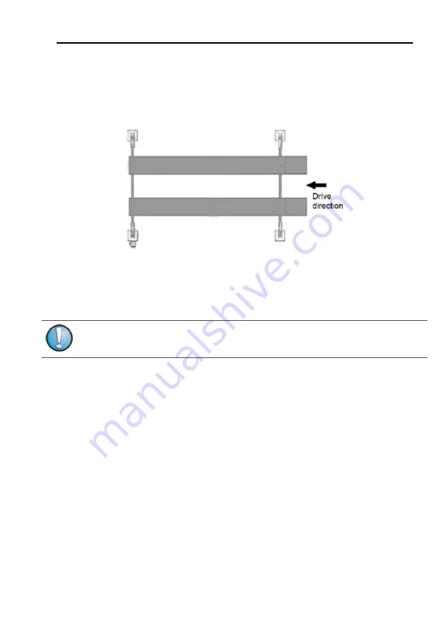
2  Slowly  position  vehicle  midway  between  platforms.  Apply  the  parking  brake  
3.  leave  vehicle  and  remain  clear  of  lift  


Always  lift  the  vehicle  using  all  four  wheels.  


Raising  

l

   Position  the  vehicle  at  the  centre  of  the  platform.     

l

   Check  to  make  sure  that  the  vehicle  is  secured.  

l

   Ensure  all  people  and  objects  are  clear  from  hoist  

l

   Place  the  pads  in  the  positions     

l

   Connect  the  power.  

l

   Press  green  button  on  power  unit  to  raise  the  vehicle     

l

   The  safety  latches  should  make  a  slight  clicking  noise  on  each  hoist  as  the  hoist  raises,  if  

they  are  not  clicking  it  is  likely  the  safety  release  lever  is  not  disengaged  fully.  

l

   To  rest  the  lift  in  standing  position  at  the  desired  height  by  releasing  the  green  button.  

l

   Press  lowering  handle  on  pump  assembly  to  lower  hoist  onto  safety  latches.  Ensure  all  four  

safety  latches  are  engaged.  

Note:

   Always   ensure   that   the   lift   rests   steadily   and   safely   latches   are   engaged   before   any  

attempt  is  made  to  work  on  or  near  the  vehicle.     

Summary of Contents for 27

Page 1: ...R POST WORKSHOP HOIST HAPP27 The manual is an integral part of the lift which it should always accompany even if the unit is sold The manual must be kept in the vicinity of the lift in an easily acces...

Page 2: ...of its legal responsibilities or obligation in accordance to the Workplace Health and Safety Act 2011 Note Thank you for participating as an early adopter of the HAPP 27 The diagrams shown in this do...

Page 3: ...loading the hoist on delivery 12 Unpacking the hoist 14 Removing the runways 15 Assembling the hoist 18 Place the cross beams on blocks in correct position in building 19 Assemble the runways onto the...

Page 4: ...ontrols 37 Electrical system 38 Limit switch wiring optional 39 Electrical wiring AS3000 40 Loading vehicle onto lift 42 Raising 42 Vehicle in raised position 43 Lowering 43 Troubleshooting 44 Hydraul...

Page 5: ...e This section should be inspected for clearance when loading your vehicle if you elect to remove this section please advise HAPP Length of Runways The HAPP27 runway length is 4 6m The length from cro...

Page 6: ...l you to disable this by connecting bridging these two wires The pump will not run unless these wires are joined If you want to add a connector later that is removable the following connector is avail...

Page 7: ...d Safety Act 2011 Intended Use The lift is designed for the safe lifting of automotive vehicles Observe the rated load capacity and load distribution of the lift Load Capacity Load distribution front...

Page 8: ...nance or repair work by authorized service personnel only l Turn off and padlock the main switch before doing any maintenance or repair work Work on electrical parts by authorized service personnel on...

Page 9: ...pictures of item and text description to admin happ com au with claim details we will advise if parts need to be sent to us In order to advise production of a fault or defect we must supply pictures a...

Page 10: ...ally for working outside The lift uses the platforms runways to support the car This machine is composed of hoisting frame and hydraulic system Main parameters Model HAPP 27 Lifting Capacity 5000kg Li...

Page 11: ...0 and 40 and must not be exposed to direct sunlight Opening the steel frame When the steel frame arrive check that the machine has not been damaged during transport and that all parts listed are prese...

Page 12: ...kage Moving and positioning operation can be very dangerous if not performed with the utmost caution Check the integrity and suitability of the available means ALL PACKING LIFTING HANDLING TRANSPORT A...

Page 13: ...n on power unit to lift the platform to 100 200mm then press unloading handle Redo it for 4 5 times and add the height 100 200 each time that can be use if it runs normally Detailed installation instr...

Page 14: ...oist length ways will require a very large fork lift or lift crane Another option described below is to use a tilt tray truck and have the driver unload into the building Figure Tilt tray truck with h...

Page 15: ...he columns pump assembly cross beams jacking beams ramps and miscellaneous parts The beams and columns are heavy ensure you place some protective board alongside the package to protect floor and items...

Page 16: ...6 Wheel chocks need rubber pads on hoist not supplied to work effectively HAPP 28 only 7 Nuts and bolts package 8 Tru bolt package 18mm bolts 9 Hose connection from pump control unit to cylinder in ma...

Page 17: ...ift HAPP27 Version 5 WWW HAPP COM AU 16 The figures below shows a procedure for rotating the runway on removal Figure removing the top runway from end frames with for lift Note carpet to minimize scra...

Page 18: ...p lift HAPP27 Version 5 WWW HAPP COM AU 17 Figure removing the bottom runway note the top runway is placed on pallets to enable easy access in subsequent steps HAPP 28 runway shown HAPP 27 does not ha...

Page 19: ...st The assembly of the hoist follows the following basic steps 1 Place the cross beams on blocks in correct position in building 2 Assemble the runways onto the crossbeams 3 Place the columns onto the...

Page 20: ...it is important to note that the pulley on the main runway will need to be slid into position YOU CANNOT LOWER THE MAIN RUNWAY INTO POSITION IT MUST BE LOWERED AT AN ANGLE AT PUMP ASSEMBLY END AND TH...

Page 21: ...les in during assembly process cross beam is sitting on blocks column not installed yet Once the main runway is in place with cables threaded the runway is bolted to the cross beam Figure bolts for co...

Page 22: ...ave runway can now be installed to the underside of the slave runway Figure guide plates for slave runway Place the columns onto the cross beams The columns can now be maneuvered into position on the...

Page 23: ...cable and press on the cable from bottom with a bar or rod to flex the cable to where it is required to fit through It may be easier to move the columns out during this process Figure Using tie wire...

Page 24: ...ift HAPP27 Version 5 WWW HAPP COM AU 23 Figure Another view of correctly threaded cable Install the cable guide pins at base of cross beam as shown below using circlip pliers to remove and reattach th...

Page 25: ...n columns with desired location Bolt main columns in to correct location ensuring aligned with cross beams and building Pull the slave columns against the main column with snap strap Align column with...

Page 26: ...vertically using builders level mark and drill the hole locations for the column If the floor is uneven use spacers to ensure the column will be plum vertically Figure Yellow snap strap used to pull t...

Page 27: ...oss beam to column clearances are correct Once the holes are drilled it is difficult to modify the location If the holes are drilled in the wrong location it there are ways to fix this but it is best...

Page 28: ...mmering through into underlying soil in need be Good accurate blows with a heavy hammer will drive the tru bolts in Once inserted tension the bolt to 80nM Fit pump assembly Before fitting the pump it...

Page 29: ...ube from end to end This mechanism is attached using two allen headed bolts at the slave beam end and two pins on the main beam end end with power unit Attach the two ends by inserting the pins into t...

Page 30: ...n the runway until the tube aligns If the safety mechanism is too firm apply lubricant or enlarge any binding points as above There is adjustment on spring returns at each column if required also The...

Page 31: ...nce the safety mechanism is connected test for fluid operation to operate the safety latch release Lower the lever to hold latches out for lowering Raise the lever to ensure latches are engaging Adjus...

Page 32: ...manual The adjustment of the cable can be set by lifting the hoist and measuring the beams at each corner and adjusting until they beams are within 10mm of each other The safety latches should engage...

Page 33: ...Four post workshop lift HAPP27 Version 5 WWW HAPP COM AU 32 Figure Vehicle loaded onto lift HAPP 28 shown...

Page 34: ...ions 1 Ambient temperature shall be 5 40 degrees Celsius 2 Humidity shall be 30 95 3 Transportation and storage temperature shall be between 25 55 degrees Celsius And short period no exceeding 24 hour...

Page 35: ...y abnormity check and exclude failure When equipment is not under work or at night descent it to the lowest position and drive the car away then turn off power supply Hoist Operating Procedures This p...

Page 36: ...r guides for regular planned maintenance Ensure checks by competent persons are performed at regular intervals or in the event of any accidental damage Isolate electrical circuits before performing ma...

Page 37: ...s hoist is not designed to be operated for outside steam cleaning or high moisture or harsh environments Vehicle hoists installed in such environments are not covered by HAPP warranty Only HAPP hoists...

Page 38: ...the power first and push the green button the power unit for up and press unloading handle on the power unit to lower the lift The small allen key in the center of one side of the unit is used to adj...

Page 39: ...ectrical system The figure below illustrates the electrical connections for the control unit on the electric motor Figure Electrical schematic for HAPP motors Some HAPP motors are supplied with an add...

Page 40: ...post workshop lift HAPP27 Version 5 WWW HAPP COM AU 39 Limit switch wiring optional Figure Limit switch wiring inside wiring of single phase motor These wires map out to a white connector as shown be...

Page 41: ...these two wires to disable the connector Electrical wiring AS3000 Power wiring will be according to the following Australian standard AS3000 Electricians must remove the top cover and verify ground n...

Page 42: ...Four post workshop lift HAPP27 Version 5 WWW HAPP COM AU 41 Wiring of single phase power to motor control unit...

Page 43: ...hoist l Place the pads in the positions l Connect the power l Press green button on power unit to raise the vehicle l The safety latches should make a slight clicking noise on each hoist as the hoist...

Page 44: ...e unloading valve on the power unit to lower the vehicle and set on the safety lock before operating on the vehicle Lowering l Be sure the safety area is free of people and objects l Raise the lift a...

Page 45: ...ill with hydraulic oil The ascend speed is slow The oil seal hole is leaking Change the oil seal Shake in the running Air in the hydraulic pressure loop Release the air by redo the ascend and decent A...

Page 46: ...HAPP COM AU 45 Hydraulic System Figure Hydraulic system for HAPP 27 Item Name Item Name Item Name 1 cylinder 4 Overflow valve 7 Gear pump 2 One way overflow valve 5 Unloading valve 8 Adjustable throt...

Page 47: ...WWW HAPP COM AU 46 Reference diagram When discussing the installation of the hoist Use the figure below for reference Figure Reference numbers for hoist discussion HAPP 28 pic shown which has extra p...

Page 48: ...f hoist To customers We ll try our best to provide customers with specific information for installation operation and maintenance to ensure that customers can use the machine without mistakes With any...

Page 49: ...cantly impact the effective operating capability of any hoist It is the owner s responsibility to ensure all regulations and requirements are met for the safe operation of the hoist and that all perso...

Reviews: