5 - 7
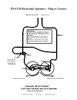
To avoid damage to Tractor or Chandler Spreader use following procedure
when hooking up the hydraulic spinner option to the tractors hydraulic system.
Hydraulic System Pumps:
Today’s tractors are equipped with either Constant Displacement or Variable Displacement
Hydraulic Pumps. Constant Displacement Pumps put out a constant flow regardless of pressure
(until the relief valve bypasses the flow). The only way to vary the flow on this type of pump is to
change the engine speed. Variable Displacement Pumps will produce only the flow required by the
implement until total pump output is reached. If less than total pump output is required, an
automatic stroke control mechanism decreases the pump output to maintain a constant pressure and
flow. The output varies according to demand.
Hydraulic Controls:
There are two types of hydraulic control or spool valve used on tractors today. They are named after
the design of the spool valves themselves. One is called “Open Center” because in the neutral (or
center) position it is open to allow flow back to the hydraulic reservoir. Open Center Valves are
used exclusively on Constant Displacement Pumps. The other valve type is called a “Closed
Center” because in the neutral (or center) position all hydraulic flow is stopped on the circuit.
Closed Center Valves are used exclusively on Variable Displacement Pumps.
There are four basic positions for each type of spool vale. They are Raise, Neutral, Lower, and Float
(in order, from back to front). The names used for these positions vary somewhat between
manufactures, but the order of the positions does not.
To properly operate a hydraulic motor on a tractor hydraulic circuit, only the
Lower
and
Float
positions should be used.
Use Lower for “On” and Float for “Off”.
The Float position is
recommend for turning the motor off because it allows the remote circuit to flow in a continuous
loop allowing the motor to free wheel to a stop and also does not trap pressure in the circuit.
Both Open and Closed Center Valves can trap oil on both sides of the circuit in the Neutral position.
Use of this position for “off” will cause premature failure or the hydraulic motor.
The Raise position is not recommend for “On” because the valve must travel through the
Neutral position to get to Float.
Many tractor hydraulic systems route return lines through filters or other restrictive elements, which
can cause an increase in the return circuit pressure. It is recommend to utilize either a standard (or
purchase an optional)
low-pressure return circuit
. This will allow for less oil heat generation,
lower horsepower consumption, and longer oil seal life.
Consult with your tractor manufacturer to see if your tractor is or can be equipped in this
way.
Summary of Contents for PT-6 FSS
Page 1: ...Model PT 6 FSS Fertilizer and Lime Spreader SERIAL __________________ WORK ORDER ___________...
Page 2: ......
Page 8: ......
Page 12: ......
Page 13: ...Fertilizer and Lime Spreader Safety...
Page 17: ...S 4 PTO SAFETY DECAL...
Page 19: ...S 6 HYDRAULIC SYSTEM DECAL...
Page 20: ...S 7 ROTATING CHAIN WARNING ROTATING SPINNERS WARNING...
Page 21: ...PTO Shaft Adjustment And Maintenance...
Page 24: ......
Page 25: ...Section 1 Basic Information...
Page 26: ...1 1 6PT FSS...
Page 27: ...1 2...
Page 29: ...Section 2 PTO Drive Spinners...
Page 33: ...2 4...
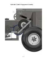
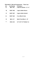
Page 36: ...2 7 Hydraulic Cylinder Engagement Assembly...
Page 38: ......
Page 39: ...PTF 71 2 RZ PTO Drive Spinner Gear Case Assembly and Parts List...
Page 43: ...Section 3 Full Press Wheel Drive Assembly...
Page 44: ...3 1...
Page 47: ...3 4...
Page 48: ...3 5...
Page 49: ...3 6 Hydraulic Cylinder Engagement Assembly...
Page 51: ...PTF 71 2 RZ FP Full Press Wheel Drive Spinner Gear Case Assembly and Parts List...
Page 55: ...Section 4 Press Wheel for Plug to Tractor Hydraulic Spinners...
Page 58: ...4 3...
Page 61: ...4 6 Hydraulic Cylinder Engagement Assembly...
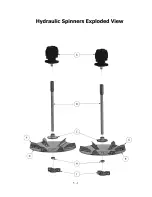
Page 63: ...Section 5 Hydraulic Spinners...
Page 64: ...5 1...
Page 67: ...5 4...
Page 68: ...5 5...
Page 74: ......
Page 75: ...Section 6 Flow Divider Assembly...
Page 76: ......
Page 77: ...5 4...
Page 79: ...Section 7 Rigid Axle Assembly...
Page 80: ...7 1 6 Bolt 7 000 per Pair Hub Assembly J I H G A F E C B D L K...
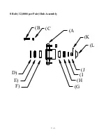
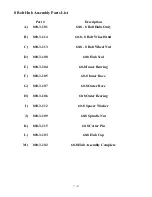
Page 82: ...7 3 8 Bolt 12 000 per Pair Hub Assembly J I H G A F E C B D L K...
Page 85: ...Section 8 Basic Set Up Operation...
Page 88: ...8 3...
Page 90: ......
Page 91: ...Section 9 Maintenance Troubleshooting...
Page 97: ...Section 10 Spread Pattern...
Page 101: ...10 4 Data Recording...
Page 102: ...10 5 Data Recording Unacceptable Pattern Acceptable Pattern...
Page 104: ...10 7 Acceptable Pattern Using a 3 Pass Switchback Driving Method...
Page 106: ...10 9 Notes...

