10 - 6
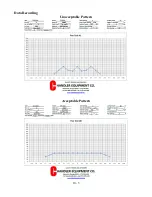
Data Recording
Using the data sheets supplied, document any and all adjustments made to the spreader
while conducting the pan test.
Using the funnel, transfer the contents of each catch pan into the corresponding test tube
for its position.
NOTE:
It is highly recommended to only make ONE adjustment between each test. If
more than one adjustment is made it will hard to determine which adjustment is
responsible for the change in spread pattern shape.
Once you’ve obtained a desirable pattern, maximum driving centers can be determined.
In order to determine the maximum swath width, locate the points on both the left and
right side of the pattern where the amount of material applied is half of the amount at
the center of the pattern. The distance between these two points represents the optimal
swath width.
If spreading blended fertilizer, a visual inspection of the samples should be conducted in
order to determine if the blend within the swath is consistent with the desired blend. If
the blend is not consistent, a narrower swath should be used and a new optimal width
should be determined.
Driving Methods
During initial testing only one pass over the pans is required. Once an optimal swath
width is determined, a multiple pass test should be conducted to check the overlap areas
of the swath.
There are different types of multiple pass driving methods; however we recommend a 3
pass switch back method. The use of this method amplifies non-symmetrical patterns by
blending right side on right and left side on left.
Summary of Contents for PT-6 FSS
Page 1: ...Model PT 6 FSS Fertilizer and Lime Spreader SERIAL __________________ WORK ORDER ___________...
Page 2: ......
Page 8: ......
Page 12: ......
Page 13: ...Fertilizer and Lime Spreader Safety...
Page 17: ...S 4 PTO SAFETY DECAL...
Page 19: ...S 6 HYDRAULIC SYSTEM DECAL...
Page 20: ...S 7 ROTATING CHAIN WARNING ROTATING SPINNERS WARNING...
Page 21: ...PTO Shaft Adjustment And Maintenance...
Page 24: ......
Page 25: ...Section 1 Basic Information...
Page 26: ...1 1 6PT FSS...
Page 27: ...1 2...
Page 29: ...Section 2 PTO Drive Spinners...
Page 33: ...2 4...
Page 36: ...2 7 Hydraulic Cylinder Engagement Assembly...
Page 38: ......
Page 39: ...PTF 71 2 RZ PTO Drive Spinner Gear Case Assembly and Parts List...
Page 43: ...Section 3 Full Press Wheel Drive Assembly...
Page 44: ...3 1...
Page 47: ...3 4...
Page 48: ...3 5...
Page 49: ...3 6 Hydraulic Cylinder Engagement Assembly...
Page 51: ...PTF 71 2 RZ FP Full Press Wheel Drive Spinner Gear Case Assembly and Parts List...
Page 55: ...Section 4 Press Wheel for Plug to Tractor Hydraulic Spinners...
Page 58: ...4 3...
Page 61: ...4 6 Hydraulic Cylinder Engagement Assembly...
Page 63: ...Section 5 Hydraulic Spinners...
Page 64: ...5 1...
Page 67: ...5 4...
Page 68: ...5 5...
Page 74: ......
Page 75: ...Section 6 Flow Divider Assembly...
Page 76: ......
Page 77: ...5 4...
Page 79: ...Section 7 Rigid Axle Assembly...
Page 80: ...7 1 6 Bolt 7 000 per Pair Hub Assembly J I H G A F E C B D L K...
Page 82: ...7 3 8 Bolt 12 000 per Pair Hub Assembly J I H G A F E C B D L K...
Page 85: ...Section 8 Basic Set Up Operation...
Page 88: ...8 3...
Page 90: ......
Page 91: ...Section 9 Maintenance Troubleshooting...
Page 97: ...Section 10 Spread Pattern...
Page 101: ...10 4 Data Recording...
Page 102: ...10 5 Data Recording Unacceptable Pattern Acceptable Pattern...
Page 104: ...10 7 Acceptable Pattern Using a 3 Pass Switchback Driving Method...
Page 106: ...10 9 Notes...


