9 - 4
C)
Remove retaining ring from flow control valve.
1)
With punch and hammer, knock lever spool from valve body.
CAUTION -
Be
sure to mark in some manner top of spool before removing.
2)
Clean thoroughly, area of housing from which lever spool was removed.
3)
Clean thoroughly the lever spool outer area and blow out all holes with high
pressure air hose.
Reassemble
as taken apart, making sure, spool is replaced with area you marked in the same
position.
If
problem has not been eliminated, continue to investigation procedure
D
.
NOTE:
The following investigation should be carried out very carefully and exactly as
outlined for there is no relief system available for this procedure and if pump is working
properly excessive pressure will build up immediately and cause damage if instructions are not
carried out precisely.
D)
Setting pressure for spinners.
1)
Run unit empty at ordinary operating speed (engine RPM’s) for approximately 10
minutes, to allow hydraulic oil to reach operating temperatures.
2)
Disengage PTO and install pressure gauge into “CF” port on flow control valve.
(Refer to hydraulic flow control valve drawing – page 3-7)
3)
Set lever on flow control valve on 10.
4)
Engage P.T.O. Rev truck engine up to approximately 2000 RPM.
5)
Slowly release clutch while watching pressure gauge.
6)
Pressure gauge should read 2000 PSI.
If
not, adjust pressure in accordance to investigation procedure
E
.
E)
Adjusting Hydraulic Flow Control Valve Pressure.
1)
Remove cap nut on flow control valve (located on top of valve)
2)
Using a 5/16” Allen wrench turn adjustment screw “IN” to increase pressure or
“OUT” to decrease pressure.
3)
Turn adjustable screw on half turn, and then check pressure setting as outlined
above.
i.
Be sure to count number of turns you adjust screw.
4)
Continue this procedure until pressure gauge reads 2000 PSI.
i.
If a 2000 PSI reading is reached on the gauge replace relief valve cover nut.
ii.
If screwing in on the relief adjusting screw had none or little effect on the
pressure, back adjusting screw out to its original position.
NOTE:
If unable to obtain 2000 PSI contact your local dealer or Chandler Equipment Service
Department at 1-800-243-3319
Summary of Contents for PT-6 FSS
Page 1: ...Model PT 6 FSS Fertilizer and Lime Spreader SERIAL __________________ WORK ORDER ___________...
Page 2: ......
Page 8: ......
Page 12: ......
Page 13: ...Fertilizer and Lime Spreader Safety...
Page 17: ...S 4 PTO SAFETY DECAL...
Page 19: ...S 6 HYDRAULIC SYSTEM DECAL...
Page 20: ...S 7 ROTATING CHAIN WARNING ROTATING SPINNERS WARNING...
Page 21: ...PTO Shaft Adjustment And Maintenance...
Page 24: ......
Page 25: ...Section 1 Basic Information...
Page 26: ...1 1 6PT FSS...
Page 27: ...1 2...
Page 29: ...Section 2 PTO Drive Spinners...
Page 33: ...2 4...
Page 36: ...2 7 Hydraulic Cylinder Engagement Assembly...
Page 38: ......
Page 39: ...PTF 71 2 RZ PTO Drive Spinner Gear Case Assembly and Parts List...
Page 43: ...Section 3 Full Press Wheel Drive Assembly...
Page 44: ...3 1...
Page 47: ...3 4...
Page 48: ...3 5...
Page 49: ...3 6 Hydraulic Cylinder Engagement Assembly...
Page 51: ...PTF 71 2 RZ FP Full Press Wheel Drive Spinner Gear Case Assembly and Parts List...
Page 55: ...Section 4 Press Wheel for Plug to Tractor Hydraulic Spinners...
Page 58: ...4 3...
Page 61: ...4 6 Hydraulic Cylinder Engagement Assembly...
Page 63: ...Section 5 Hydraulic Spinners...
Page 64: ...5 1...
Page 67: ...5 4...
Page 68: ...5 5...
Page 74: ......
Page 75: ...Section 6 Flow Divider Assembly...
Page 76: ......
Page 77: ...5 4...
Page 79: ...Section 7 Rigid Axle Assembly...
Page 80: ...7 1 6 Bolt 7 000 per Pair Hub Assembly J I H G A F E C B D L K...
Page 82: ...7 3 8 Bolt 12 000 per Pair Hub Assembly J I H G A F E C B D L K...
Page 85: ...Section 8 Basic Set Up Operation...
Page 88: ...8 3...
Page 90: ......
Page 91: ...Section 9 Maintenance Troubleshooting...
Page 97: ...Section 10 Spread Pattern...
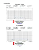
Page 101: ...10 4 Data Recording...
Page 102: ...10 5 Data Recording Unacceptable Pattern Acceptable Pattern...
Page 104: ...10 7 Acceptable Pattern Using a 3 Pass Switchback Driving Method...
Page 106: ...10 9 Notes...


