8 - 2
Setting Spinner Speed – Hydraulic Spinners Only
We recommend a spinner speed of
650–725 RPM
as this unit is designed for a 50ft.
spread pattern for fertilizer and a 30ft. pattern for lime. This spreader is equipped with a
flow control valve to adjust spinner speed and to maintain a constant speed after your
tractor reaches proper PTO RPM’s. Generally the flow control valve will need to set at
about 6, however due to machining tolerances, this setting will vary from one spreader
to the next.
Spinner speed should be set following these guidelines:
1)
Rev engine speed to proper PTO RPM (540/1000).
a.
Before starting engine be sure that there is no material or obstructions in
bed or on spinners.
2)
Take a hand tach reading on spinner shaft.
a.
Spinners shafts are center drilled underneath the spinners to accept a hand
tach.
b.
If unit has a
control system
with spinner speed sensor and spinner speed
read out, this can be used in place of hand tach reading.
3)
Adjust lever on flow control valve until desired speed is reached - the higher the
indicator number the faster the spinners should run.
4)
After getting correct spinner speed, increase tractor engine RPMs to proper PTO
RPM (540/1000) - spinner speed should remain within reason of the desired
speed.
5)
If spinner speed does not remain constant within reason, disassemble flow control
valve and clean parts as outlined under
Troubleshooting Procedures
, Problem I,
investigations
B
and
C
.
NOTE:
In some instances, due to density of materials, a faster or slower spinner
speed may be desired. If so, follow above procedures and set speed accordingly.
CAUTION:
Due to normal wear, the setting on the flow control valve may need
to be set higher as time goes by. Check spinner speed often.
CAUTION:
Spinner speed is one of the most important factors in achieving a
proper spread pattern and must be set properly and checked regularly.
NOTE:
If the spinners are running too fast you will tend to leave a thin streak
behind the center of the tractor, if they are too slow it will leave a heavy streak.
Record Valve Setting ____________
Summary of Contents for PT-6 FSS
Page 1: ...Model PT 6 FSS Fertilizer and Lime Spreader SERIAL __________________ WORK ORDER ___________...
Page 2: ......
Page 8: ......
Page 12: ......
Page 13: ...Fertilizer and Lime Spreader Safety...
Page 17: ...S 4 PTO SAFETY DECAL...
Page 19: ...S 6 HYDRAULIC SYSTEM DECAL...
Page 20: ...S 7 ROTATING CHAIN WARNING ROTATING SPINNERS WARNING...
Page 21: ...PTO Shaft Adjustment And Maintenance...
Page 24: ......
Page 25: ...Section 1 Basic Information...
Page 26: ...1 1 6PT FSS...
Page 27: ...1 2...
Page 29: ...Section 2 PTO Drive Spinners...
Page 33: ...2 4...
Page 36: ...2 7 Hydraulic Cylinder Engagement Assembly...
Page 38: ......
Page 39: ...PTF 71 2 RZ PTO Drive Spinner Gear Case Assembly and Parts List...
Page 43: ...Section 3 Full Press Wheel Drive Assembly...
Page 44: ...3 1...
Page 47: ...3 4...
Page 48: ...3 5...
Page 49: ...3 6 Hydraulic Cylinder Engagement Assembly...
Page 51: ...PTF 71 2 RZ FP Full Press Wheel Drive Spinner Gear Case Assembly and Parts List...
Page 55: ...Section 4 Press Wheel for Plug to Tractor Hydraulic Spinners...
Page 58: ...4 3...
Page 61: ...4 6 Hydraulic Cylinder Engagement Assembly...
Page 63: ...Section 5 Hydraulic Spinners...
Page 64: ...5 1...
Page 67: ...5 4...
Page 68: ...5 5...
Page 74: ......
Page 75: ...Section 6 Flow Divider Assembly...
Page 76: ......
Page 77: ...5 4...
Page 79: ...Section 7 Rigid Axle Assembly...
Page 80: ...7 1 6 Bolt 7 000 per Pair Hub Assembly J I H G A F E C B D L K...
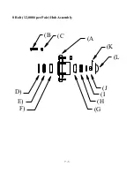
Page 82: ...7 3 8 Bolt 12 000 per Pair Hub Assembly J I H G A F E C B D L K...
Page 85: ...Section 8 Basic Set Up Operation...
Page 88: ...8 3...
Page 90: ......
Page 91: ...Section 9 Maintenance Troubleshooting...
Page 97: ...Section 10 Spread Pattern...
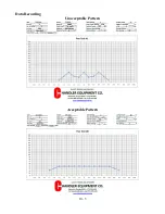
Page 101: ...10 4 Data Recording...
Page 102: ...10 5 Data Recording Unacceptable Pattern Acceptable Pattern...
Page 104: ...10 7 Acceptable Pattern Using a 3 Pass Switchback Driving Method...
Page 106: ...10 9 Notes...

