3
c.
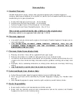
Dealer shall be responsible for informing the customer of operating procedures, safety precautions
and normal maintenance to help avoid any warranty issues.
d.
Promptly inform Chandler Equipment of any possible warranty issues.
e.
Dealer is
responsible for making every effort to resolve warranty issues in a timely manner.
f.
Notify Chandler Equipment on any possible non-warranty issues, such as any modification made to
equipment.
F)
Original Chandler
Genuine Parts:
a.
Chandler Equipment Company will only warranty equipment that uses Chandler Genuine Parts. Any
equipment that is sold by a dealer with parts other than Original Chandler Genuine parts shall Void
Any and All warranties
G)
Replacement Parts Shipping:
a.
Chandler Equipment Company shall send Chandler Genuine Parts for warranty replacement.
Chandler Equipment shall NOT warranty any part or parts replaced by the Customer/Dealer that are
not Chandler Genuine Parts.
b.
Cost of any part or parts that are replaced by the Customer / Dealer that are not Chandler Genuine
Parts shall be the sole responsibility of the Customer / Dealer.
All replacement parts covered under warranty will be shipped via regular UPS. The cost of any parts
shipped
UPS-Next Day Air
will be the sole responsibility of the Customer/Dealer.
H)
Parts Returns:
a.
All parts replaced under warranty will be returned to Chandler Equipment Company within 20 days
of replacement for warranty evaluation. All parts returned for warranty evaluation must be in its
original state free of modifications. Any modifications will result in the warranty claim being denied
and the part or parts returned back to the customer/dealer.
b.
Any hydraulic components returned must be assembled (in original state) and with the ports plugged
to prevent any contamination. Any hydraulic component that has been disassembled will VOID the
warranty claim and the part or parts returned back to the customer/dealer.
c.
All Returned Parts for warranty evaluation must be clearly tagged with the following information.
I.
RMA number
II.
Customer or Dealer Name, address, phone number and contact person
III.
Equipment serial number
IV.
Complete description of problem
I)
Misuse or Improper Installation:
a.
Any equipment, parts, or components that have been damaged by improper installation or misuse
will
NOT
be covered under this warranty.
b.
Chandler Equipment accepts no responsibility or liability of any kind due to improper installation of
equipment or parts on any product manufactured by Chandler Equipment Company. This includes,
but is not limited to, any damages to personal property, crops, or any other equipment.
Summary of Contents for PT-6 FSS
Page 1: ...Model PT 6 FSS Fertilizer and Lime Spreader SERIAL __________________ WORK ORDER ___________...
Page 2: ......
Page 8: ......
Page 12: ......
Page 13: ...Fertilizer and Lime Spreader Safety...
Page 17: ...S 4 PTO SAFETY DECAL...
Page 19: ...S 6 HYDRAULIC SYSTEM DECAL...
Page 20: ...S 7 ROTATING CHAIN WARNING ROTATING SPINNERS WARNING...
Page 21: ...PTO Shaft Adjustment And Maintenance...
Page 24: ......
Page 25: ...Section 1 Basic Information...
Page 26: ...1 1 6PT FSS...
Page 27: ...1 2...
Page 29: ...Section 2 PTO Drive Spinners...
Page 33: ...2 4...
Page 36: ...2 7 Hydraulic Cylinder Engagement Assembly...
Page 38: ......
Page 39: ...PTF 71 2 RZ PTO Drive Spinner Gear Case Assembly and Parts List...
Page 43: ...Section 3 Full Press Wheel Drive Assembly...
Page 44: ...3 1...
Page 47: ...3 4...
Page 48: ...3 5...
Page 49: ...3 6 Hydraulic Cylinder Engagement Assembly...
Page 51: ...PTF 71 2 RZ FP Full Press Wheel Drive Spinner Gear Case Assembly and Parts List...
Page 55: ...Section 4 Press Wheel for Plug to Tractor Hydraulic Spinners...
Page 58: ...4 3...
Page 61: ...4 6 Hydraulic Cylinder Engagement Assembly...
Page 63: ...Section 5 Hydraulic Spinners...
Page 64: ...5 1...
Page 67: ...5 4...
Page 68: ...5 5...
Page 74: ......
Page 75: ...Section 6 Flow Divider Assembly...
Page 76: ......
Page 77: ...5 4...
Page 79: ...Section 7 Rigid Axle Assembly...
Page 80: ...7 1 6 Bolt 7 000 per Pair Hub Assembly J I H G A F E C B D L K...
Page 82: ...7 3 8 Bolt 12 000 per Pair Hub Assembly J I H G A F E C B D L K...
Page 85: ...Section 8 Basic Set Up Operation...
Page 88: ...8 3...
Page 90: ......
Page 91: ...Section 9 Maintenance Troubleshooting...
Page 97: ...Section 10 Spread Pattern...
Page 101: ...10 4 Data Recording...
Page 102: ...10 5 Data Recording Unacceptable Pattern Acceptable Pattern...
Page 104: ...10 7 Acceptable Pattern Using a 3 Pass Switchback Driving Method...
Page 106: ...10 9 Notes...


