Hameg HM304 Manual Download Page 17

17

Subject to change without notice

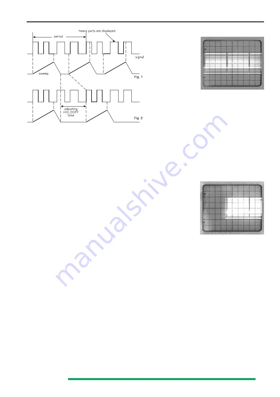
Fig. 1 shows a case where the HOLD OFF knob is in the
minimum position (x1) and various different waveforms are
overlapped on the screen, making the signal observation
unsuccessful.
Fig. 2 shows a case where only the desired parts of the signal
are stably displayed.

Delay / After Delay Triggering

As mentioned before, triggering starts the time base sweep
and unblanks the beam. After the maximum X deflection to
the right, the beam is blanked and flies back to the (left) start
position. After the hold off period the  sweep is started
automatically by the automatic trigger or the next trigger
signal. In normal triggering mode the  automatic trigger is
switched off and will only start on receipt of a trigger signal.

As the trigger point is always at the trace start position, trace
expansion in X direction with the aid of the timebase is limited
to the display on the left of the trace. Parts of the signal to
be expanded which are displayed  near the trace end (right
side of the screen) are lost when the timebase speed is
increased (time coefficient  reduced).

The delay function delays the trace start by a variable time
from the trigger point. This allows the sweep  to begin on
any portion of a signal. The timebase speed can then be
increased to expand the display  in X direction. With higher
expansion rates, the intensity reduces and within certain limits
this can be compensated by the 

INTENS

 knob setting.

If the display shows jitter, it is possible to select for (second)
triggering after the elapsed delay time (DTR).
As mentioned before, it is possible to display video signals
using the frame sync pulses for triggering (TV-F). After  the
delay time set by the operator, the next line sync pulse or
the line content may be used for triggering. So data lines and
test lines can be displayed separately.

Operation of the delay function is relatively simple. Without
delay function (no LED on the DELAY scale in the X field lit)
set the time coefficient setting (

TIME/DIV

) until 1 to 3 signal

periods are displayed. Display of less the one period should
be avoided as it limits the selection of the signal section to
be expanded, and may cause trigger problems.

The X MAG (x10) function should be switched off and the
time variable control should be in CAL position. The signal must
be triggered and stable. The following explanation assumes
that the trace starts on the left vertical graticule line.

Photo 1 (composite video signal)

MODE: undelayed
TIME/DIV: 5ms/div
Trigger coupling: TV-F
Trigger slope: falling ( - )

Depressing the DELAY pushbutton once for a short time,
lights the 

SEA (SEARCH) LED

 on the DELAY scale. In  all

delay modes, the 

DEL. POS.

 knob assumes the function of

DEL. POS.

 (delay position), and the hold off time defaults to

x1. Now the function of this knob 

(DEL. POS.)

 is to adjust the

delay time, indicated as a blanked part of the screen. The length
of the blanked sector depends on the 

DEL. POS.

 setting and

can be set between approx. one and six division after the nor-
mal trace start position. As the trace right end is not effected,
the visible trace length is reduced. In delay (DEL) mode, the
trace will start from the normal left end where the blanking
starts. If the maximum delay is not sufficient, the time
coefficient must be increased (TIME/DIV left arrow pushbutton)
and the 

DEL. POS. 

knob set to the later starting point. To

return to normal (undelayed operation), depress the 

DELAY

pushbutton for a longer time or step through the different

DELAY

 functions until no 

LED

 on the 

DELAY

 scale is lit.

Photo 2

MODE: SEA (SEARCH)
TIME/DIV: 5ms/div
Trigger coupling: TV-F
Delay time:
4div x 5ms = 20ms

Photo 2 shows that the delay time can be measured. It is
identical with the delayed position of the trace start and can
be calculated by multiplying the delay length measured in
div. and the actual calibrated time coefficient.
If in search (

SEA

) mode the next short depression of the

DELAY pushbutton switches over to DEL (

LED

 lit).

The blanked period indicating the delay time is switched off
and the trace has its normal - unreduced-, lenght.
The trace starts on its previous X position (without 

DELAY

mode), beginning with the signal part first visible in  search
(

SEA

) mode after the delay time. When the delay (

DEL

) mode

is in operation, it might even maximum intensity may not be
sufficient. In this case the timebase speed should be reduced
by increasing the time coefficient  (

TIME/DIV

), to a slower

speed.

As mentioned before, the main purpose of the delay mode is
to make signal magnification in X direction possible.
This is the reason why the time coefficient in DEL mode
cannot be set to higher values than used during 

SEA

 (search)

operation. 

DEL

 mode speeds must always be faster.

Please note that the previous time coefficient chosen in DEL
and DTR mode is stored and automatically set after activating
one of those modes. If the stored time coefficient in 

DEL

 or

Summary of Contents for HM304

Page 1: ...tructions General Information 5 Symbols 5 Use of tilt handle 5 Safety 5 Operating conditions 5 EMC 6 Warranty 6 Maintenance 6 Protective Switch Off 6 Power supply 6 Type of signal voltage 7 Amplitude...

Page 2: ...uction in the manual for a reduced cable length the maximum cable length of a dataline must be less than 3 meters long If an interface has several connectors only one connector must have a connection...

Page 3: ...nzt durch 93 68 EWG Low Voltage Equipment Directive 73 23 EEC amended by 93 68 EEC Directive des equipements basse tension 73 23 CEE amend e par 93 68 CEE Angewendete harmonisierte Normen Harmonized...

Page 4: ...35MHz 3dB Risetime 10ns Overshoot max 1 Deflection coefficients 14 calibrated steps from1mV div to20V div 1 2 5 sequence with variable 2 5 1 up to 50V div Accuracy in calibrated position 1mV div to 2m...

Page 5: ...three conductor power cord with protective earthing conductor and a plug with earthing contact The mains line plug shall only be inserted in a socket outlet provided with a protective earth contact T...

Page 6: ...aintenance Various important properties of the oscilloscope should be carefully checked at certain intervals Only in this way is it largely certain that all signals are displayed with the accuracy on...

Page 7: ...ms Veff have 2 83 times the potential difference in Vpp The relationship between the different voltage magnitudes can be seen from the following figure Voltage values of a sine curve Vrms effective va...

Page 8: ...e base setting indicated by one of the TIME DIV LED s one or several signal periods or only a part of a period can be displayed The time coefficients are stated in s div when the red sec LED and the 0...

Page 9: ...hes next to the edge are also not taken into account With very severe transient distortions the rise and fall time measurement has little meaning For amplifiers with approximately constant group delay...

Page 10: ...oscilloscope by depressing the red POWER pushbutton The instrument will revert to its last used operating mode Except in the case of COMP TESTER mode where a trace appears on the screen if the INTENS...

Page 11: ...should be adjusted The location of the low frequency compensation trimmer can be found in the probe information sheet Adjust the trimmer with the insulated screw driver provided until the tops of the...

Page 12: ...channell I to channel II and vice versa after each sweep period In DUAL mode the internal trigger source can be switched over from channel I to channel II and vice versa if the TRIG pushbutton is dep...

Page 13: ...compared with C short circuited then the test voltage leads the reference voltage and vice versa This applies only in the region up to 90 phase shift Therefore C should be sufficiently large and produ...

Page 14: ...t when external trigger is used the trigger threshold can be stated as vertical display height in div through which the time base generator starts the display is stable and the trigger LED located in...

Page 15: ...gnals than the DC coupling because the white noise in the trigger voltage is strongly suppressed So jitter or double triggering of complex signals is avoidable or at least reduced in particular with v...

Page 16: ...er voltage may have a completely different form from the test signal voltage Triggering is even possible in certain limits with whole number multiples or fractions of the test frequency but only with...

Page 17: ...following explanation assumes that the trace starts on the left vertical graticule line Photo 1 composite video signal MODE undelayed TIME DIV 5ms div Trigger coupling TV F Trigger slope falling Depre...

Page 18: ...ted in Dual mode under conditions where DUAL chopped mode is active this display mode is not switched off when time coefficients are being reduced 0 2ms div to 0 05 s div for signal expansion in DEL a...

Page 19: ...also be made to integrated circuits All these components can be tested in and out of circuit The test principle is fascinatingly simple A built in generator delivers a sine voltage which is applied a...

Page 20: ...ore testing of transistor amplification is not possible but testing of a single junction is easily and quickly possible Since the test voltage applied is only very low all sections of most semiconduct...

Page 21: ...ould then be connected to the insulated COMP TESTER socket avoiding hum distortion of the test pattern Another way is a test pattern comparison to an identical circuit which is known to be operational...

Page 22: ...Subject to change without notice 22...

Page 23: ...of astigmatism A certain loss of marginal sharpness of the CRT is unavoidable this is due to the manufacturing process of the CRT Symmetry and Drift of the Vertical Amplifier Both of these characteri...

Page 24: ...eck of the mono channel display is unnecessary it is contained indirectly in the tests above stated Triggering Checks The internal trigger threshold is important as it determines the display height fr...

Page 25: ...and also the influence of the earths magnetic field which is dependent on the instruments North orientation are corrected by means of the TR potentiometer In general the trace rotation range is asymme...

Page 26: ...hanged Generally max halving or doubling of this resistance value should be sufficient A too small trigger threshold cause double triggering or premature trigger action due to interference pulses or r...

Page 27: ...R ckgabe Beschreibung PC Scope Scope PC ID ID Daten CR LF data consits of instrument type manufacturer CR R CR LF remote status and baud rate acceptance TRSTA TRSTA b CR LF query for trigger status d...

Page 28: ...nter 0 13 CH2 GND AC INV2 ON VALUE Counter 0 13 mv DIV 0000 20V DIV 1101 MODE CT XY A TR CHOP ADD 0 TR SOURCE 00 Y1 01 Y2 1x EXT TB1 x10 0 0 TB A TIME Counter 1 26 50ns DIV 00 bis 0 5s DIV 15hex TB2 0...

Page 29: ...cy ranges AC 10Hz 100MHz DC 0Hz 100MHz HF 1 5kHz 100MHz LF 0Hz 1 5 kHz TV L to trigger on line sync pulses TV F to trigger on separated frame sync pulses Select SLOPE for the leading slope Sync pulse...

Page 30: ...control for trace sharpness mechanical knob TR Trace rotation mechanical To align trace with horzontal field potentiometer graticule line Compensates adjustment with influence of Earth s magnetic scr...

Page 31: ...triggering Not available in combination with ext triggering XY or COMP TESTER modes INPUT CH II Channel II signal input BNC connector Input impedance 1M II 20pF AC DC Selects input coupling of CH II...

Reviews: