


13
Subject to change without notice
are identical for both the X and Y axes. However, the
Y-POS.II
control is disconnected in this mode. Its function is taken
over by the
X-POS.
control. It is important to note that the
X-MAG. (x10)
facility, normally used for expanding the
sweep, is inoperative in the X-Y mode. It should also be noted
that the bandwidth of the X amplifier is
≤
2.5MHz (-3dB), and
therefore an increase in phase difference between both axes
is noticeable from 50kHz upwards.
The inversion of the X-input signal using the
INV CH.II
button
is not possible.
Lissajous figures can be displayed in the
X-Y
mode for certain
measuring tasks:
•
Comparing two signals of different frequency or bringing
one frequency up to the frequency of the other signal.
This also applies for whole number multiples or fractions
of the one signal frequency.
•
Phase comparison between two signals of the same
frequency.
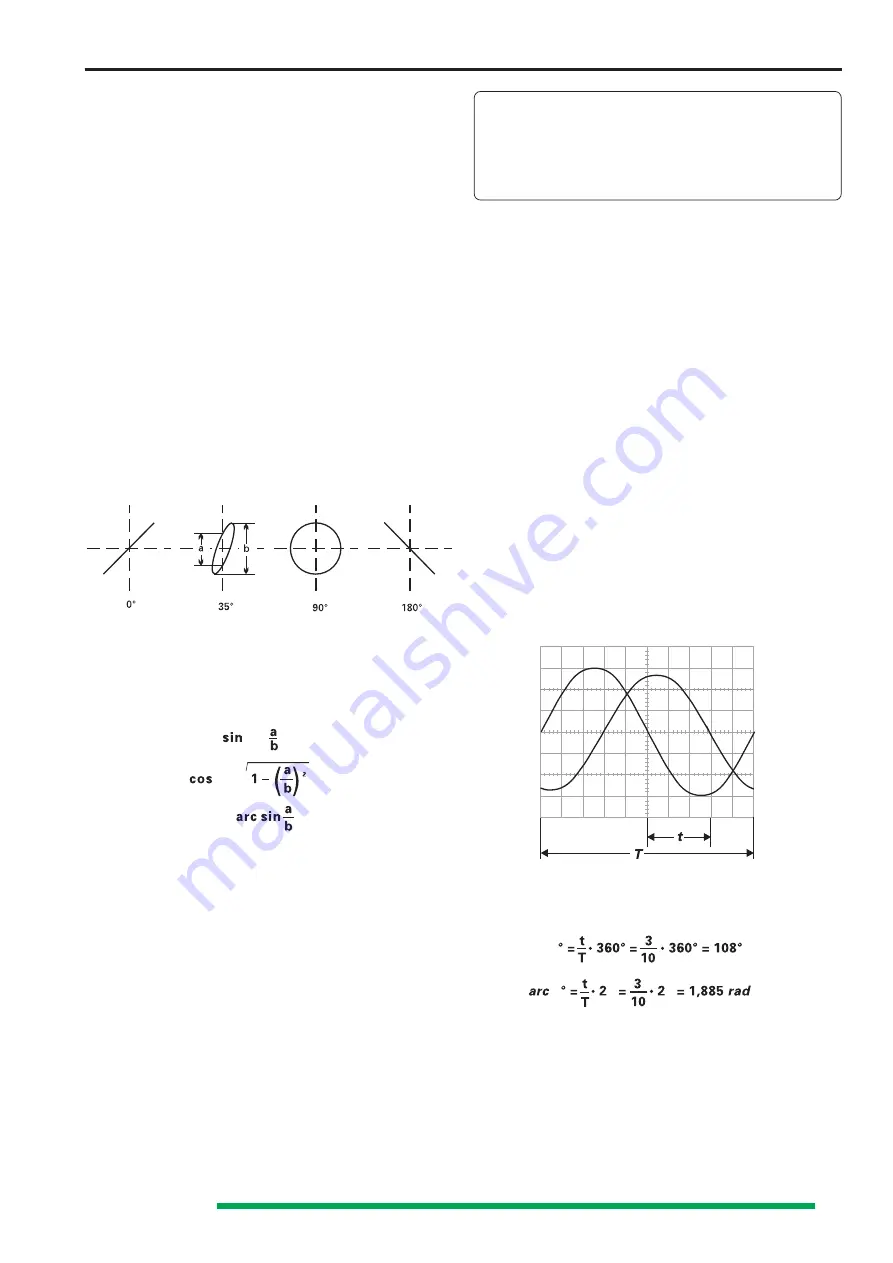
Phase comparison with Lissajous figures
The following diagrams show two sine signals of the same
frequency and amplitude with different phase angles.
Calculation of the phase angle or the phase shift between
the X and Y input voltages (after measuring the distances a
and b on the screen) is quite simple with the following
formula, and a pocket calculator with trigonometric functions.
Apart from the reading accuracy, the signal height has no
influence on the result.
The following must be noted here:
•
Because of the periodic nature of the trigonometric
functions, the calculation should be limited to angles
≤
90°
However here is the advantage of the method.
•
Do not use a too high test frequency. The phase shift of
the two oscilloscope amplifiers of the HM304 in the X-Y
mode can exceed an angle of 3° above 120kHz.
•
It cannot be seen as a matter of course from the screen
display if the test voltage leads or lags the reference
voltage. A CR network before the test voltage input of
the oscilloscope can help here. The 1 M
Ω
input resistance
can equally serve as R here, so that only a suitable
capacitor C needs to be connected in series. If the
aperture width of the ellipse is increased (compared with
C short-circuited), then the test voltage leads the
reference voltage and vice versa. This applies only in the
region up to 90° phase shift. Therefore C should be
sufficiently large and produce only a relatively small just
observable phase shift.
Should both input voltages be missing or fail in the X-
Y mode, a very bright light dot is displayed on the
screen. This dot can burn into the phosphor at a too
high brightness setting (INTENS. knob) which causes
either a lasting loss of brightness, or in the extreme
case, complete destruction of the phosphor at this
point.
Phase difference measurement
in DUAL mode
A larger phase difference between two input signals of the
same frequency and shape can be measured very simply on
the screen in Dual mode. The time base should be triggered
by the reference signal (phase position 0). The other signal
can then have a leading or lagging phase angle.
For greatest accuracy adjust slightly over one period and
approximately the same height of both signals on the screen.
The variable controls for amplitude and time base and the
TRIG. LEVEL
knob can also be used for this adjustment
without influence on the result. Both base lines are set onto
the horizontal graticule center line with the
Y-POS.
knobs
before the measurement. With sinusoidal signals, observe
the zero (crossover point) transitions; the sine peaks are less
accurate. If a sine signal is noticeably distorted by even
harmonics, or if a
DC
voltage is present,
AC
coupling is
recommended for both channels. If it is a question of pulses
of the same shape, read off at steep edges.
It must be noted that the phase difference cannot be
determined if alternate triggering (
TR I
and
TR II
lit) is selected.
Phase difference measurement in DUAL mode
t
= horizontal spacing of the zero transitions in div.
T
= horizontal spacing for one period in div.
In the example illustrated, t = 3div. and T = 10div. The phase
difference in degrees is calculated from
Relatively small phase angles at not too high frequencies can
be measured more accurately in the X-Y mode with Lissajous
figures.
Measurement of an
amplitude modulation
The momentary amplitude u at time t of a HF-carrier voltage,
which is amplitude modulated without distortion by a
sinusoidal AF voltage, is in accordance with the equation
ϕ =
ϕ = √
ϕ =
ϕ
ϕ
π
π


