


80
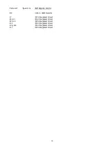
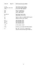
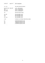
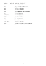
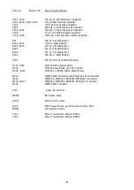
Parts List:
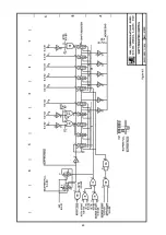
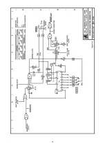
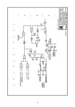
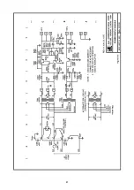
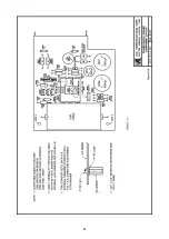
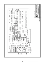
Figure 8.11:
Morse Output Control
C17
2.2 µF, 16 Volt Electrolytic Capacitor
C17A
4.7 µF, 25 Volt Electrolytic Capacitor
C302, C303
0.001 µF Disc Ceramic Capacitor
C304
10 µF, 16 Volt Electrolytic Capacitor
R39, R42, R43B, R43C
100 Ω, ¼ Watt Resistor
R40
390 Ω, ¼ Watt Resistor
R41
270 Ω, ¼ Watt Resistor
R43
1 kΩ, ¼ Watt Resistor
R43A
4.7 kΩ, ¼ Watt Resistor
P1
500 Ω Trim-Pot, Vertical Mounting
P302
500 Ω Linear Potentiometer, with Switch (Volume Control)
D9
1N4148 Silicon Signal Diode
D10
1N4005 Silicon Power Diode
Q4
MPS3703 or MPS6518 PNP Transistor
Q5
2N5655 or MJE340 NPN Transistor
Q6
2N5401 PNP Transistor
I18, I55
7400 Integrated Circuit
I24
7404 Integrated Circuit
J302, J303
¼" Phone Jack, 1-circuit with NO contact
J304
Phono Jack
SP301
2" Speaker, 8 or 25 Ω impedance
Summary of Contents for DKB-2010
Page 1: ......
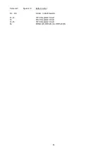
Page 20: ...18...
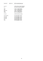
Page 39: ...37 Table 4 3 ROM Converter Input and Output Codes...
Page 52: ...50 Figure 6 1 Logic Circuit Board Test Points...
Page 53: ...51 Figure 6 2 Keyswitch Circuit Board Test Points...
Page 54: ...52 Figure 6 3 Power Supply Circuit Board Test Points...
Page 57: ...55 Table 6 4 DKB 2010 Wire List...
Page 63: ...61...
Page 64: ...62...
Page 65: ...63...
Page 67: ...65...
Page 69: ...67...
Page 71: ...69...
Page 73: ...71...
Page 75: ...73...
Page 77: ...75...
Page 79: ...77...
Page 81: ...79...
Page 83: ...81...
Page 85: ...83...
Page 87: ...85...
Page 89: ...87...
Page 91: ...89...
Page 92: ...90...
Page 93: ...91...
Page 94: ...92...
Page 95: ...93...
Page 96: ...A1 EXTENDED MEMORY OPTION FOR THE DKB 2010 KEYBOARD INSTRUCTION MANUAL...
Page 100: ...A5...
Page 101: ...A6...


