


33
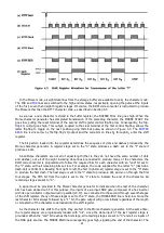
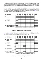
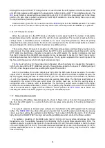
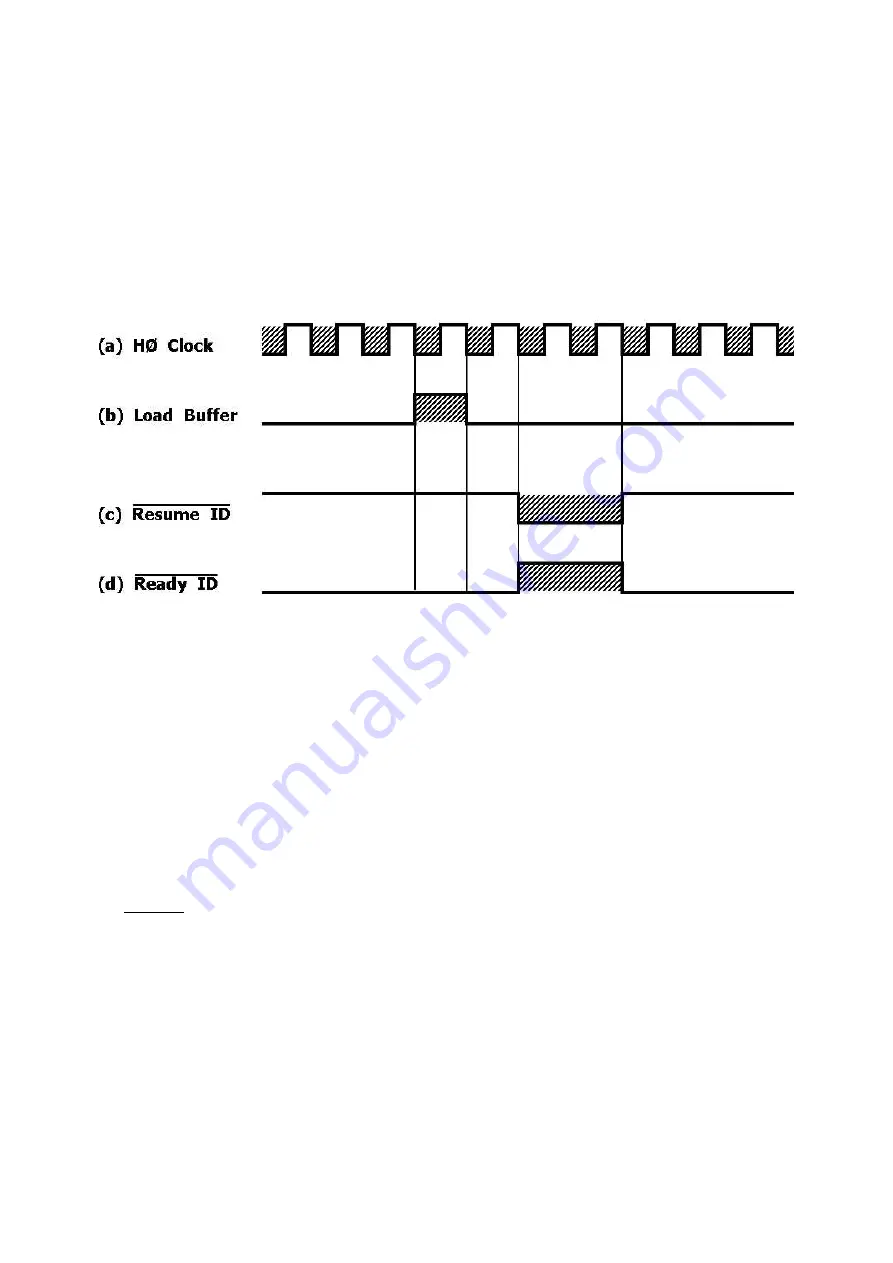
The input pulses are derived from the buffer control circuit because the identifier must be instructed to
produce each successive output code only when the buffer is ready to receive it. Characters are loaded from
the ROM code converter into the buffer when the LOAD BUFFER line goes high momentarily. As shown in
Figure 4.10, the
RESUME ID
line goes low for two HØ clock pulses shortly after the character has been
loaded. This signal is inverted to produce the
READY ID
signal, which clocks the QBF counter. The counter
increments, providing a new character at the storage buffer input. After the preceding character has been
transmitted, the LOAD BUFFER line goes high again, and the new character enters the buffer. The process
continues until the test message is completed.
When the counter has received 63 such pulses, all counter Q outputs are high. The output of gate IC-51
goes low, driving the
ENABLE KEYBOARD
line high and preventing further clock pulses from reaching the
counter. The cycle of operation is then complete, and, unless the QBF key is held down, the keyboard is
restored to normal operation.
Figure 4.10 Development of Clock Pulses for Automatic Character Sequencers
Since the ROM is coded to produce only RTTY codes for the QBF message, the output is
incomprehensible when the keyboard is in the Morse code. The input from the
QUICK BROWN FOX START
line is disabled in that case by a high level on the M/R line applied to pin 3 of IC-54. The counters cannot be
reset and the circuit remains inactive.
It is not possible, however, to predict the states the counter stages will assume when the power is first
switched on; the circuit may start in the active state. To clear the counter quickly in the Morse mode, the
VHØ clock signal is supplied to a NAND gate (pin 1 of IC-52), If the QBF circuit is active, indicated by a high
level on pin 13 of the gate, and if the keyboard is in the Morse mode, indicated by a high level on the M/R
line pin 2, the VHØ clock signal is applied to the counter input, so that the counter very rapidly increments
until it reaches its 64th state. It then becomes inactive and normal Morse operation can begin.
4.15 Identifier
The circuit which automatically transmits the station identification message operates on a principle quite
similar to that of the QBF generator. The character codes, however, are not stored in the ROM code
converter, instead, a diode matrix read-only memory is used so that the message may be altered if desired
by simply repositioning the diodes in the memory matrix. The matrix output produces the ASCII code for the
message characters. These codes are supplied to the ROM code converter on data lines A
0
through A
6
in
place of those normally produced by the keyboard encoder. The circuit is shown in Figure 8.13.
The identification sequencer uses a four-bit counter, the output states of which are decoded by IC's 40
and 42. As the counter increments, the decoder output lines go low in sequence. Each line represents one
character in the stored message.
Diodes are connected from each line to the A
0
through A
6
data lines in those positions required to
produce the ASCII code for the character. When the decoder line goes low, those A lines to which diodes
are connected go low also. When the converted character code has entered the storage buffer, the counter
Summary of Contents for DKB-2010
Page 1: ......
Page 20: ...18...
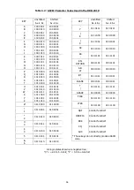
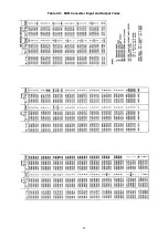
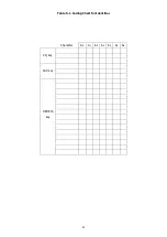
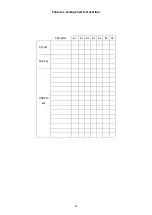
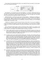
Page 39: ...37 Table 4 3 ROM Converter Input and Output Codes...
Page 52: ...50 Figure 6 1 Logic Circuit Board Test Points...
Page 53: ...51 Figure 6 2 Keyswitch Circuit Board Test Points...
Page 54: ...52 Figure 6 3 Power Supply Circuit Board Test Points...
Page 57: ...55 Table 6 4 DKB 2010 Wire List...
Page 63: ...61...
Page 64: ...62...
Page 65: ...63...
Page 67: ...65...
Page 69: ...67...
Page 71: ...69...
Page 73: ...71...
Page 75: ...73...
Page 77: ...75...
Page 79: ...77...
Page 81: ...79...
Page 83: ...81...
Page 85: ...83...
Page 87: ...85...
Page 89: ...87...
Page 91: ...89...
Page 92: ...90...
Page 93: ...91...
Page 94: ...92...
Page 95: ...93...
Page 96: ...A1 EXTENDED MEMORY OPTION FOR THE DKB 2010 KEYBOARD INSTRUCTION MANUAL...
Page 100: ...A5...
Page 101: ...A6...