


30
The
7
output of the decoder is fed back to the clock input of the oscillator control flip-flop. When the
counter has received seven clock pulses, the
7
line goes low. On the eighth clock pulse, it returns to the
high state. This positive transition will cause the oscillator control flip-flop to reset if the end of the character
has been reached, stopping the oscillator. If not, the low level on the MORSE END line holds the flip-flop's
preset terminal low, the flip-flop remains set, and the oscillator continues to run to produce the next dot or
dash. The "0" output of the dot flip-flop is coupled through a NAND gate to the MORSE CHARACTER line,
which carries the signal to the Morse output control circuit. It is ultimately used to activate the transmitter
keying transistor.
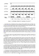
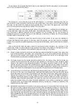
If the shift register output is high during the operation just described, the clear input to the dash flip-flop
(pin 13 of IC-22) is held low, preventing any change of state. If, on the other hand, the character to be
produced is a dash, the shift register output is low, and the dash flip-flop is free to toggle when the DOT
line goes high, as shown in Figure 4.8. The dash flip-flop then divides the dot line frequency by two. The
DASH
line and the
DOT
line are supplied to two inputs of a NAND gate (pins 4 and 5 of IC-18). During the
production of dots, the
DASH
line is held high, and the output of the dot flip-flop is coupled through the
gate to the Morse character bus. For dashes, both flip-flops are active, and the two output lines are logically
added in the gate, as shown in trace g of Figure 4.8.
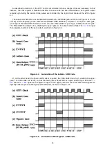
At the end of each complete Morse character, it is necessary to include a space equal in length to three
dots. After all character bits have been clocked from the shift register to the Morse generator, the MORSE
END line goes high and thus can no longer hold the oscillator control flip-flop in the set state. However,
recall that an extra "1" bit (the end bit) is loaded into the shift register in the position immediately following
the last character bit. The SHIFT REGISTER bus is fed to one input of the NOR gate which drives the control
flip-flop preset terminal. The clock therefore continues to run for eight additional oscillator pulses, as shown
in Figure 4.9 , producing an extra dot. This dot is passed to a NAND gate in the Morse output control circuit,
where it is combined with the
MORSE END
signal. Since the latter line goes low at the end of the character
bits the extra dot does not pass to the gate output and is not transmitted.
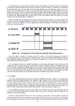
The MORSE CHARACTER output is inverted in a NOR gate (part of IC-8) to produce the
MORSE SHIFT
signal. Fed back to the shift register, it causes the register to shift at the end of each dot or dash, providing
the bit for the next Morse pulse to the input of the character generator. The waveform drawing included in
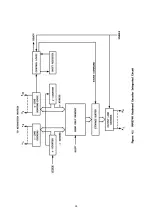
Figure 8.10 shows the key signals for generation of the Letter K (dash-dot-dash).
Figure 4.8 Production of Dashes by the Morse Character Generator
Summary of Contents for DKB-2010
Page 1: ......
Page 20: ...18...
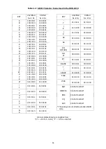
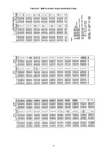
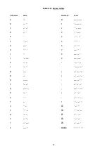
Page 39: ...37 Table 4 3 ROM Converter Input and Output Codes...
Page 52: ...50 Figure 6 1 Logic Circuit Board Test Points...
Page 53: ...51 Figure 6 2 Keyswitch Circuit Board Test Points...
Page 54: ...52 Figure 6 3 Power Supply Circuit Board Test Points...
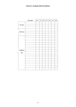
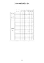
Page 57: ...55 Table 6 4 DKB 2010 Wire List...
Page 63: ...61...
Page 64: ...62...
Page 65: ...63...
Page 67: ...65...
Page 69: ...67...
Page 71: ...69...
Page 73: ...71...
Page 75: ...73...
Page 77: ...75...
Page 79: ...77...
Page 81: ...79...
Page 83: ...81...
Page 85: ...83...
Page 87: ...85...
Page 89: ...87...
Page 91: ...89...
Page 92: ...90...
Page 93: ...91...
Page 94: ...92...
Page 95: ...93...
Page 96: ...A1 EXTENDED MEMORY OPTION FOR THE DKB 2010 KEYBOARD INSTRUCTION MANUAL...
Page 100: ...A5...
Page 101: ...A6...