


3
ILLUSTRATIONS (continued)
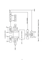
Figure 8.1: DKB-2010 Block Diagram ........................................................... 61
Figure 8.2: Drawing Conventions ................................................................. 62
Figure 8.3: Keyboard Encoder ..................................................................... 63
Figure 8.4: ROM Code Converter and Buffer Control ...................................... 65
Figure 8.5: RTTY Control and Decoder ......................................................... 67
Figure 8.6: Shift Register Control ................................................................. 69
Figure 8.7: RTTY Encoder and Loop Interface ............................................... 71
Figure 8.8: RTTY Timing Chain .................................................................... 73
Figure 8.9: RTTY Character Counter ............................................................ 75
Figure 8.10: Morse Character Generator ........................................................ 77
Figure 8.11: Morse Output Control ................................................................ 79
Figure 8.12: Quick Brown Fox Generator and ID Control ................................. 81
Figure 8.13: Identifier .................................................................................. 83
Figure 8.14: Three-Character Sequencers ...................................................... 85
Figure 8.15: Power Supply Module ................................................................ 87
Figure 8.16: Power Supply Board Component Layout ..................................... 89
Figure 8.17: Keyboard Circuit Board Component Layout ................................. 90
Figure 8.18: Keytop Positions ....................................................................... 91
Figure 8.19: Main Logic Board Component Layout - IC's ................................. 92
Figure 8.20: Main Logic Board Component Layout - Small Parts ...................... 93
TABLES
Table 3.1: Characters Produced by Bracketed Keys ...................................... 13
Table 4.1: RTTY Timing Chain Output Frequencies ....................................... 27
Table 4.2: ASCII Character Codes Used in the DKB-2010 .............................. 36
Table 4.3: ROM Character Input and Output Code ....................................... 37
Table 4.4: RTTY Baudot Codes ................................................................... 38
Table 4.5: Morse Codes ............................................................................. 39
Table 5.1: Coding Chart for Identifier .......................................................... 41
Table 6.1: Test Points - Logic Circuit Board ................................................. 49
Table 6.2: DKB Logic Board Connector (J305) .............................................. 53
Table 6.3: DKB Keyboard Connector (J306) and DKB Power Supply (J307) .... 54
Table 6.4: DKB-2010 Wire List .................................................................... 55
Table 6.5: Integrated Circuit Pin Numbers for Ground And Power .................. 56
Summary of Contents for DKB-2010
Page 1: ......
Page 20: ...18...
Page 39: ...37 Table 4 3 ROM Converter Input and Output Codes...
Page 52: ...50 Figure 6 1 Logic Circuit Board Test Points...
Page 53: ...51 Figure 6 2 Keyswitch Circuit Board Test Points...
Page 54: ...52 Figure 6 3 Power Supply Circuit Board Test Points...
Page 57: ...55 Table 6 4 DKB 2010 Wire List...
Page 63: ...61...
Page 64: ...62...
Page 65: ...63...
Page 67: ...65...
Page 69: ...67...
Page 71: ...69...
Page 73: ...71...
Page 75: ...73...
Page 77: ...75...
Page 79: ...77...
Page 81: ...79...
Page 83: ...81...
Page 85: ...83...
Page 87: ...85...
Page 89: ...87...
Page 91: ...89...
Page 92: ...90...
Page 93: ...91...
Page 94: ...92...
Page 95: ...93...
Page 96: ...A1 EXTENDED MEMORY OPTION FOR THE DKB 2010 KEYBOARD INSTRUCTION MANUAL...
Page 100: ...A5...
Page 101: ...A6...