


17
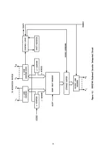
Depending on the setting of the mode switch, the register output activates either the Morse character
generator or the RTTY loop switching circuit. In the RTTY mode, the output code keys the loop switch
through an isolation circuit. For Morse transmission, the bits must be converted to pulses of unequal length,
forming dots and dashes. The Morse character generator accepts the serial code from the shift register and
performs the conversion. The generator output activates the Morse keying transistor and the sidetone
oscillator.
Several additional circuits are included to increase operating convenience. In the RTTY mode, a counter
keeps track of the number of characters transmitted after a carriage return. It activates the RTTY END OF
LINE lamp and triggers a toneburst from the sidetone oscillator when 64 characters have been produced.
The "quick brown fox" generator produces the standard RTTY test message when the QBF key is
pressed. A similar automatic character sequencer, usable in both the RTTY and Morse modes, produces the
letters DE and the station call sign whenever the operator strikes the HERE IS key. Two other automatic
sequencers produce three-character groups at a single keystroke. One is normally coded to transmit the
letters CQ followed by a space. The other, activated by the AUX key, may be programmed for any group of
three characters of the user's choice by rearranging diodes in a memory matrix. All of the sequencers will
repeat their messages as long as the activating keyswitch is held down.
4.3 Circuit Analysis
In the following sections, the keyboard circuitry will be described in greater detail. In the course of the
discussion, frequent reference is made to the schematic diagrams included in Section 8. Figure 8.2, which
precedes the schematics, illustrates the drawing conventions used.
To aid in tracing signal paths through the keyboard circuit diagrams, each line which connects between
portions of the circuit shown on different drawings is designated by a name that describes its function (e.g.,
BUFFER FULL). Some of the labels are overscored, indicating that the signal carried by the line is inverted or
"negative true". Thus the BUFFER FULL line is at its "high" level (above 2,4 Volt) when a character has been
stored in the buffer register. On the other hand, the line designated
RTTY TONE
activates the tone
generator when it changes to its "low" state (less than 0.8 Volt).
To aid in locating the source of the signals on these lines, a code is included with the name, except, of
course, at the point where the signal originates. The code consists of a number and a dash, followed by a
letter and number pair (for example, 8.1-B3). The first number indicates the figure in which the signal
source may be found – in this case Figure 8.1. Each schematic diagram includes coordinates, similar to
those used on maps, along two of its edges, The letter-number pair of the code gives the coordinates of the
area on the drawing where the signal originates. In the case of the code 8.1-B3, the signal source may be
found in Section B3 of Figure 8.1.
Two signal lines which deserve special attention are the M/R line and its inverted counterpart, the
M/R
line. The signal on these buses switches the keyboard between the Morse and the RTTY mode, disabling the
RTTY circuits when the mode switch is set to the Morse position, and the Morse circuits when it is set to one
of the RTTY operating speeds, the M/R bus is high in the Morse mode and low in the RTTY mode; the
M/R
line assumes the opposite states.
Most of the keyboard circuit components and wiring are contained on two printed circuit boards. The
boards are interconnected by a wiring harness with a card-edge connector at each end. The harness also
connects to the cabinet-mounted components and to the power supply. Small squares containing a single
letter or number appear on some signal lines to indicate that the line is connected to the harness through
one of the edge connectors. The number or letter in the square corresponds to the connector pin
designation.
The keyboard encoder is included on the circuit board to which the key-switches are mounted. All other
circuitry, except for cabinet mounted parts, is found on the other boards. A wire list of the harness
connections is included at the end of Section 8.
Summary of Contents for DKB-2010
Page 1: ......
Page 20: ...18...
Page 39: ...37 Table 4 3 ROM Converter Input and Output Codes...
Page 52: ...50 Figure 6 1 Logic Circuit Board Test Points...
Page 53: ...51 Figure 6 2 Keyswitch Circuit Board Test Points...
Page 54: ...52 Figure 6 3 Power Supply Circuit Board Test Points...
Page 57: ...55 Table 6 4 DKB 2010 Wire List...
Page 63: ...61...
Page 64: ...62...
Page 65: ...63...
Page 67: ...65...
Page 69: ...67...
Page 71: ...69...
Page 73: ...71...
Page 75: ...73...
Page 77: ...75...
Page 79: ...77...
Page 81: ...79...
Page 83: ...81...
Page 85: ...83...
Page 87: ...85...
Page 89: ...87...
Page 91: ...89...
Page 92: ...90...
Page 93: ...91...
Page 94: ...92...
Page 95: ...93...
Page 96: ...A1 EXTENDED MEMORY OPTION FOR THE DKB 2010 KEYBOARD INSTRUCTION MANUAL...
Page 100: ...A5...
Page 101: ...A6...