


29
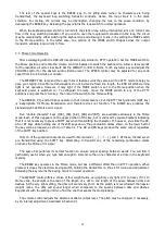
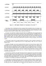
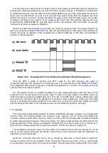
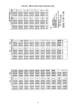
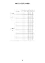
Figure 4.6 Morse Clock and Decoder Waveform
The
0
output of IC-31 is connected through an inverter to the J input of the dot flip-flop. The output
from one of the remaining lines is selected by the weight control (S302), inverted, and fed to the K input.
When the counter is in the "0" state, the dot flip-flop's J input is therefore high and its K input is low.
On the first negative-going clock transition, the dot flip-flop assumes the state of its J and K inputs; that
is, it toggles to the "1" state, as shown in Figure 4.7. The DOT line, connected to the toggle input of the
dash flip-flop (pin 11 of IC-22) goes high.
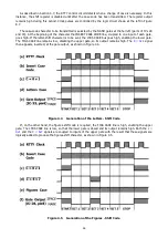
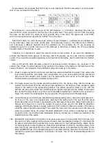
Figure 4.7 Production of Dots by the Morse Character Generator
Assuming for the moment that S302 is set for normal weight, the K input of the flip-flop is driven by
decoder output
4
(pin 5). During the next three clock pulses, the flip-flop does not change states because
its J and K inputs are held low. After clock pulse 3, however, the decoder
4
output goes low, driving the flip-
flop's K input high. On the next negative-going clock transition, the flip-flop changes back to its original
state, pulling the DOT line low. The flip-flop does not revert to the set condition until the counter has
completed its cycle and a new bit has been supplied by the shift register. The dot pulse is therefore followed
by a space.
Because it is possible to select which decoder input is used to reset the dot flip-flop, the duty cycle of the
output may be varied. The duration of the dot as compared to that of the following space may be set for
any ratio from 1:7 to 3:1. Four of the six possible weight ratios are selectable by the weight switch, as
determined by the position of the jumpers on the circuit board.
Summary of Contents for DKB-2010
Page 1: ......
Page 20: ...18...
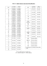
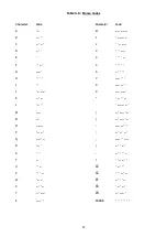
Page 39: ...37 Table 4 3 ROM Converter Input and Output Codes...
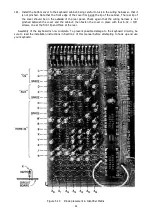
Page 52: ...50 Figure 6 1 Logic Circuit Board Test Points...
Page 53: ...51 Figure 6 2 Keyswitch Circuit Board Test Points...
Page 54: ...52 Figure 6 3 Power Supply Circuit Board Test Points...
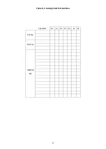
Page 57: ...55 Table 6 4 DKB 2010 Wire List...
Page 63: ...61...
Page 64: ...62...
Page 65: ...63...
Page 67: ...65...
Page 69: ...67...
Page 71: ...69...
Page 73: ...71...
Page 75: ...73...
Page 77: ...75...
Page 79: ...77...
Page 81: ...79...
Page 83: ...81...
Page 85: ...83...
Page 87: ...85...
Page 89: ...87...
Page 91: ...89...
Page 92: ...90...
Page 93: ...91...
Page 94: ...92...
Page 95: ...93...
Page 96: ...A1 EXTENDED MEMORY OPTION FOR THE DKB 2010 KEYBOARD INSTRUCTION MANUAL...
Page 100: ...A5...
Page 101: ...A6...