Page 2
INSTALLATION
1)
Install HLC Switches and Controllers
Install the HLC Dimmers and Switches, 6-Button Room Controllers, and 8-Button House Controllers according to the instructions
that came with each device.
2)
Install the HLC Phase Coupler
Install the supplied HLC Phase Coupler (P/N: 39A00-1) according to the instructions that came with the unit.
3)
Mount the Lumina Enclosure
Mount the Lumina enclosure securely to the wall in the selected location using screws and wall anchors, as appropriate.
4)
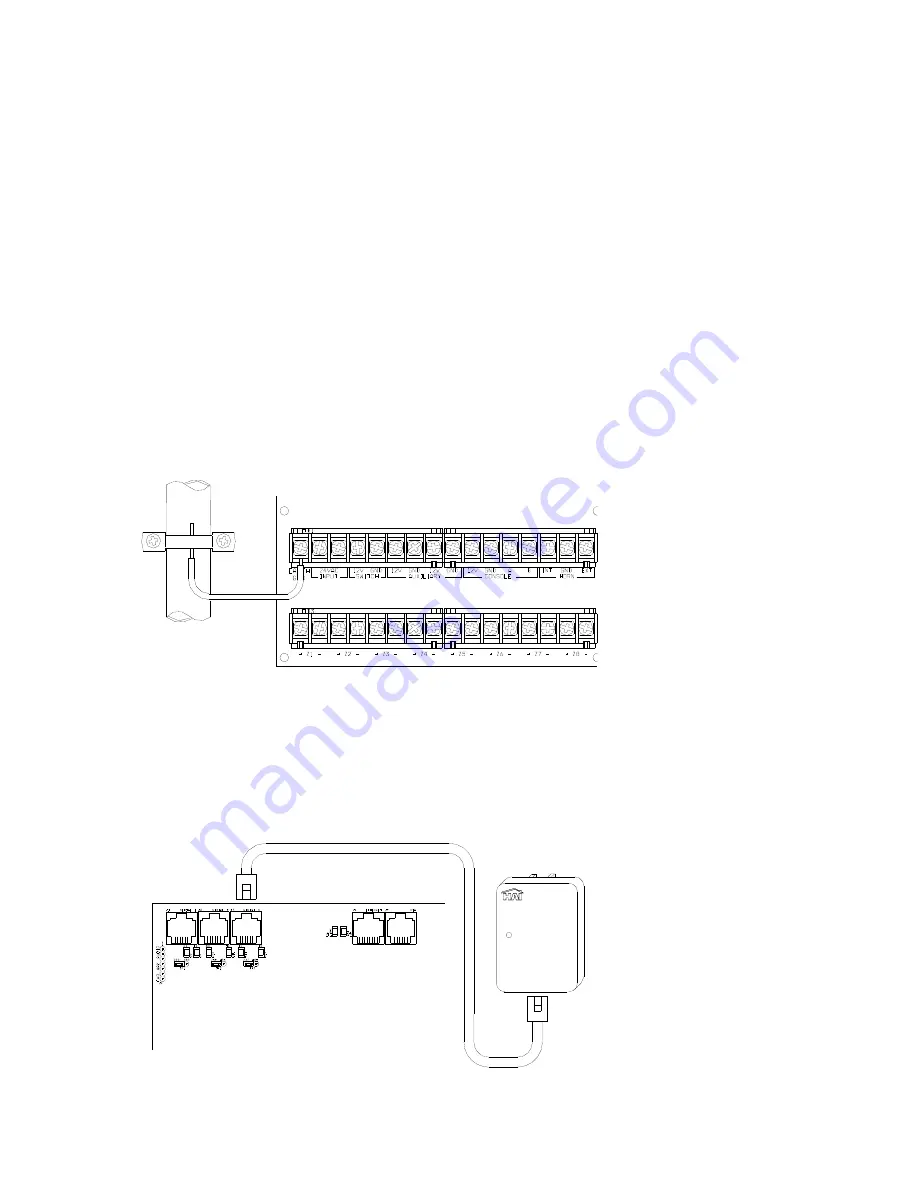
Ground the Lumina Controller
GROUND THE LUMINA CONTROLLER’S "EARTH GND" TERMINAL TO A COLD WATER PIPE OR TO A 4-FOOT
GROUND ROD TO PRESERVE ITS BUILT-IN TRANSIENT PROTECTION. USE 14 GAUGE WIRE. TRANSIENT
PROTECTION WILL NOT WORK IF THE CONTROLLER IS NOT PROPERLY GROUNDED.
ACCORDANCE WITH THE NATIONAL
ELECTRIC CODE, ANSI/NFPA 70.
COLD WATER PIPE
OR GROUND ROD
GOUNDING METHOD MUST BE IN
5)
Connect the Powerline Interface Module (PIM) to the Lumina
Locate the supplied PIM (P/N: 36A00-1). Plug the PIM into a 120 VAC outlet. Plug one end of the supplied 6-conductor
modular cable into the connector marked “J3” (SERIAL 3) on the Lumina controller and plug the other end into the modular
connector on the PIM as shown.
6 CONDUCTOR
<Program
Status
Powerline Interface Module
UPB™


