IV.
OPERATING SYSTEMS
31
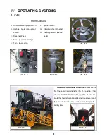
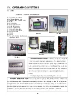
VENTS–
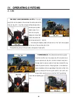
There are 6 adjustable vents, 3 on each
front cab corner post (fig. 31-1). They may be adjusted
by rotating them for desired direction, or individually
turned on or off with the directional fins.
RADIO-
The cab has AM/FM tuner equipped with a
CD player and Weather Band broadcasting. Refer to the
radio manufacturer’s manual for operating and program-
ming information.
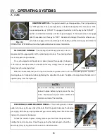
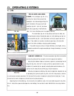
RAVEN SPRAY SYSTEMS CONSOLE–
The spray system is
controlled by the Raven SCS 4600 (fig. 31-3)
and the Pulse Width Modulated Valve (fig. 31-
4). The system receives data and automatically
makes adjustments based on the target rate of
application set by the operator.
For detailed information regarding the pro-
gramming and operating of the Raven console
system, please refer to the manufacturer’s installation and operation manual.
FIG. 31-3
FIG. 31-4
A. CAB
FIG. 31-1
FIG. 31-2
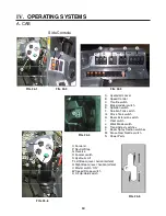
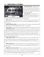
TASSELTROL CONTROL BOX/ DETASSELING SWITCH
PANEL-
The detasseling heads and lift assemblies are controlled by
the Hagie Tasseltrol ®/LS System 12 (fig. 31-5, item B) and the controls
on the detasseler switch box assembly (fig. 31-5, item A). Refer to sec-
tion B under SYSTEM PROGRAMMING for details on the Hagie Tas-
seltrol® box. Continue reading this section for detailed information on
the functions of the switches.
These controls are changed out with the Raven console when the
detasseling option is being used. Refer to section D under OPERATING SYSTEMS for detailed information on
switching the control panels.
When either of the panels are not in use, store them in a safe and dry place. Excessive moisture may
cause corrosion of the electrical components. Before plugging a control panel into the machine’s electrical
system, check the panel for damage such as a loose or cut wire or corrosion. If damage exists, do not connect
the panel as it may cause a short in the system and could potentially cause a fire.
A
B
FIG. 31-5

