background image

IV. 

 OPERATING SYSTEMS 

28 

A. CAB 

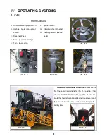
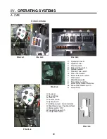
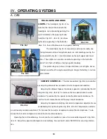
Overhead Controls and Monitors 

FIG. 28-4 

FIG. 28-1 

FIG. 28-2 

A. 

Hagie Diagnostic Port


B. 

Warning Indicator Light


C. 

Spray System Indicator Light


D. 

MDM


E. 

Wiper switch


F. 

Washer Fluid switch


G. 

Field Lights switch


H. 

Work Lights switch


I. 

Climate Control– fan


J. 

Climate Control– temp


K. 

Raven Console


L. 

Radio


M. 

Vents


N. 

Tasseltrol Control Box/ Detassel-
ing Switch Panel


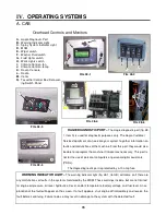
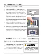
HAGIE DIAGNOSTIC PORT– 

The Hagie diagnostic port (fig. 28-

1, item A) is used for diagnostic purposes only. The Hagie Customer 

Service department can hook into your system to gather information on 

faults and malfunctions of the machine. From this port, they would also 

be able to reprogram the machine if it becomes necessary. This port is 

not for the use of personal computers or personal digital assistants 

(PDA’s).  


The Hagie diagnostic port is protected by a 10 amp fuse.  


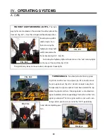
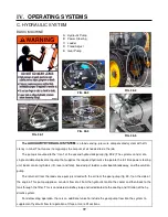
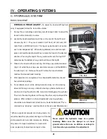
WARNING INDICATOR LIGHT– 

The warning indicator light (fig. 28-1, item B) will come on if there are 

any malfunctions or faults in the systems monitored by the MDM. These warnings include, but are not limited 

to: engine oil pressure, oil level, hydraulic oil level, coolant temperature, battery voltage, and fuel level. An ex-

planation of the fault will appear on the screen. If a fault appears, shut engine off immediately and resolve the 

fault before continuing. Failure to do so may result in damage to the system with the detected fault.   

FIG. 28-3 

FIG. 28-5 

FIG. 28-6 

Summary of Contents for UpFront STS 14 Combo

Page 1: ...related accessories contain lead and lead compounds chemicals known to the State of California to cause cancer and birth defects or other reproductive harm ANY PICTURES CONTAINED WITHIN THIS OPERATOR...

Page 2: ...UAL FOR HAGIE MODEL STS 14 HI TRACTOR SPRAYER DETASSELER 02 09 493423 2007 Hagie Manufacturing Company Clarion Iowa USA 721 CENTRAL AVENUE WEST BOX 273 CLARION IOWA 50525 515 532 2861 COVERS MACHINE S...

Page 3: ...INCH INFO INFORMATION Km H KILOMETERS PER HOUR L LITER DISPLACEMENT l LITER LIQUID LB POUND LS LIGHT SENSOR m METER MAINT MAINTENANCE MIN MINUTE M F MAINFRAME MPH MILES PER HOUR MT MOUNT MTH MONTH MTR...

Page 4: ...ning condition We have attempted herein to cover all of the adjustments required to fit varying conditions However there may be times when special care must be considered Hagie Manufacturing Company r...

Page 5: ...e this manual should accompany the sprayer If you do not understand any part of the manual or require additional information or service contact the Hagie Customer Support Department Hagie Manufacturin...

Page 6: ...AFETY DECALS DRIVING Before moving sprayer make sure no persons or obstructions are in path of travel Do not permit passengers on sprayer when it is moving they may fall off or obstruct operator s vie...

Page 7: ...ettings Operate engine at one bump to assure proper charge pressure for brakes to work properly Start engine from operator s seat only Do not by pass safety start switch Never use starting fluid to as...

Page 8: ...refueling Do not smoke while refueling Do not fill fuel tank completely Fuel may expand and run over GENERAL REPAIR MAINTENANCE Turn off engine before checking adjusting repairing lubricating or clean...

Page 9: ...or spray residue from sprayer to prevent corrosion and deterioration Select a safe area to fill flush calibrate and clean sprayer where chemicals will not drift or run off to contaminate people animal...

Page 10: ...lowing are locations of important safety de cals Replace them if they are torn or missing All warning decals and other instructional Hagie decals or machine striping may be purchased through Hagie Cus...

Page 11: ...I SAFETY DECALS 6 650165 Right side rear cab post 650174 In engine compartment on radiator 650164 Left side rear cab post...

Page 12: ...I SAFETY DECALS 7 650176 Inside right hand cab post by rear window 650178 Quick attach mount 650218 2 1 each end of the combo attachment...

Page 13: ...On hydraulic reservoir to left of sight gauge picture 2 650339 On front cross member left side picture 1 1 2 I SAFETY DECALS 8 Right side window rear corner 650379 650303 Right side window rear corner...

Page 14: ...9 650848 On ladder pivot tube 2 on each cutter head housing 650819 Quad puller head 650820 I SAFETY DECALS...

Page 15: ...I SAFETY DECALS 10 650849 On engine compartment near fuel cell cap 650850 On solution tank near fill lid 1 front fill On inductor tank lid 2 side fill 1 2...

Page 16: ...I SAFETY DECALS 11 650982 650981 In engine compartment near radiator cap 650851 Left rear mainframe On fuel cell near batteries Fuel cell...

Page 17: ...e identifica tion plates that describe the type of mount and gear ratio To ensure prompt efficient service when or dering parts or requesting service repairs from Hagie Manufacturing Company record th...

Page 18: ...ERS 13 Front Rear Wheel Hubs Left Right Front Rear Hydrostatic Pumps Refer to parts manual Front Wheel Motors Left Right Refer to parts manual Rear Wheel Motors Left w Sensor Right w Sensor Sauer hydr...

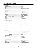
Page 19: ...e Hydrostatic pump Sauer Danfoss Tandem 90 series Displacement 150cc 75 X 2 with electronic displacement control Drive train All time four wheel drive Speed ranges 3 work mode 4 transport mode Hydrost...

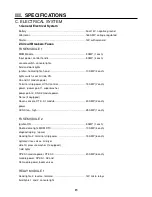
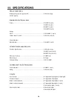
Page 20: ...wer power point 1 wiper washer power point 2 XS A2 module power Norac if equipped Raven console XT2 A1 module 20 AMP 2 each power HVAC fan high 25 AMP 1 each FUSE MODULE 2 Ignition ON 5 AMP 1 each Rad...

Page 21: ...her light harness 12V flasher relay 15 AMP fuse 4 each 40 AMP relay 3 each Main rear harness 30 AMP fuse Main chassis 5V relay Console Relay 15V 100 AMP COMBO UNIT ELECTRICAL BOX Circuit Breaker 20 AM...

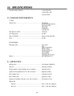
Page 22: ...ure Ground speed Engine RPM Tread adjustment assist Stereo AM FM WB with CD Solution tank 1400 gallons 5299 58 Fuel cell 150 gallons 530 Cooling system including block lines radiator 18 gallons 68 Hyd...

Page 23: ...fill connection 3 in 7 6 cm I D 3 Solution Tank Standard 1400 gal 5299 58 stainless steel w sight gauge Agitation stainless steel tank Sparge type w elect var speed control 4 General Spray System Pum...

Page 24: ...raulic couplers 2 Outriggers 12 Row 134 1 Left 1Right 8 Row 75 1 Left 1 Right 3 Quad Puller Number of rows available 8 10 or 12 Drive Hydraulic Tire size 4 10 3 50 2 ply Operating speed Up to 400 RPM...

Page 25: ...5 kg Overall diameter 72 6 in 2042 2 mm Static load radius suggested will vary with load 33 8 in 947 42 mm Rolling circumference 219 0 in 6147 mm Optional wide 580 70R38 Radial TU Air pressure 23 PSI...

Page 26: ...em A Ac tivate the hazard warning lights anytime day or night that you are traveling on a public road unless prohib ited by law FIG 21 6 A Hazard Warning light switch B Highway lights running light sw...

Page 27: ...ot a self cen tering switch you must return it to the OFF position by hand after completing your turn FIG 22 4 FIG 22 5 HIGHWAY LIGHTS RUNNING LIGHTS The high way lights are mounted on the cab and the...

Page 28: ...e movement of the upper portion of the steering column only The steering wheel has infinite position possibilities To use the adjustment handle turn it down toward the operator to loosen it You do not...

Page 29: ...Float switch J Work Mode switch K Tread Adjust switches L Boom Spray Section switches M Fence Row Nozzle switch N Power Ports FIG 24 1 A B C D O Forward P Neutral Stop Q Reverse R Foamer switch S Hydr...

Page 30: ...to OPER ATING SYSTEMS section B on the hydrostatic drive system FIG 25 2 THROTTLE SWITCH The throttle switch fig 25 3 is used to control engine RPM There are 2 set tings that are controlled by the sw...

Page 31: ...on if certain conditions exist You can not turn the switch on if the machine is not in neutral The switch controls the func tions of the spray system and detasseling system This was set up to protect...

Page 32: ...drostatic lever is responsible for the direction of motion of the machine To move forward slowly move the hy drostatic lever forward fig 27 2 item F REVERSE CONTROL To move the machine in reverse slow...

Page 33: ...ns of the machine From this port they would also be able to reprogram the machine if it becomes necessary This port is not for the use of personal computers or personal digital assistants PDA s The Ha...

Page 34: ...k spray pattern and adjust at the beginning of each spray season or as necessary FIG 29 3 FIG 29 4 FIG 29 5 A CAB SPRAY SYSTEM INDICATOR LIGHT The spray system indicator light fig 29 1 item A will ill...

Page 35: ...ended FIG 30 1 A B FIG 30 2 FIG 30 3 CLIMATE CONTROLS The climate controls fig 30 4 are continu ous adjusting dial switches located on the front upper cab headliner Adjusting Fan Blower Speed fan blow...

Page 36: ...AB FIG 31 1 FIG 31 2 TASSELTROL CONTROL BOX DETASSELING SWITCH PANEL The detasseling heads and lift assemblies are controlled by the Hagie Tasseltrol LS System 12 fig 31 5 item B and the controls on t...

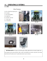
Page 37: ...eat E Cab Fresh Air Filters F Interior Lights G Air Ride Seat FIG 32 3 INTERIOR LIGHTS The cab has two interior lights A dome light that comes on when the door of the cab is opened and a courtesy ligh...

Page 38: ...e front windshield is rounded with a green UV reflective tint and the side and back panels are flat with a UV reflective gray tint The design of the cab and the use of the glass allows a 210 view tip...

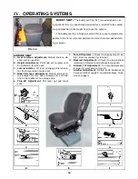
Page 39: ...Push knob in to raise seat C Lateral Isolator Lift lever to engage lateral isola tor Push lever down for lock out D Ride Firmness Adjustment Rotate knob coun terclockwise for firm ride clockwise for s...

Page 40: ...e sel engine fig 35 1 equipped with an automatic exhaust brake The engine has a direct mounted Sauer Danfoss 90 Series tandem hydro static pump fig 35 2 More information on the operation of the engine...

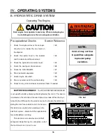
Page 41: ...engine from operator s seat only When running engine in a building be sure there is adequate ventilation 123 125 123 128 127 129 135 139 NOTE Cold oil may not flow in quantities adequate to prevent pu...

Page 42: ...it to start light in the message center fig 37 3 to go out before engaging the starter If the engine fails to start after 15 seconds turn the key to OFF wait one minute and repeat the procedure If the...

Page 43: ...ull the hydrostatic lever back To stop slowly push the lever to the N neutral position 5 Before turning off the engine reduce engine speed and allow the engine to idle at least three minutes NOTE Mach...

Page 44: ...oom control cylinders lift level and fold tread adjust ladder outer boom breakaway and the solution pump The return oil from the load sense pump is mixed with the oil from the gear pump fig 39 1 on th...

Page 45: ...rvoir drops too low to safely operate the machine you must shut down the engine immediately to prevent damage to the hydraulic system POWER STEERING SYSTEM The power steering is a dedicated circuit st...

Page 46: ...the switch when the tread indicator reaches the desired tread marking 4 After adjustment is complete all four tread width indicators should have identical readings 5 To recalibrate toe in while drivi...

Page 47: ...or cleaning so lution from the rinse tank through the rinse systems FIG 42 3 IV OPERATING SYSTEMS C HYDRAULIC SYSTEM 42 SPRAY SYSTEM A Solution Pump B Boom Control Valve C Spray Booms FIG 42 3 B BOOM...

Page 48: ...d in the sprayer s cab and hydraulic cylinders attached to the booms It provides control of lift level horizontal extension and vertical extension All STS spray booms are equipped with a hydraulic bre...

Page 49: ...s guide for information regarding spray tip height fig 44 3 To raise and lower the transom boom assembly depress the square rocker on the hydrostatic lever fig 44 1 and move it either UP or DOWN Whil...

Page 50: ...und Rocker UP or the left or right Round Rocker DOWN buttons on the hydrostatic lever fig 45 3 While depressed these buttons activate the level cylinders connecting either boom to the transom fig 45 2...

Page 51: ...ress the right or left Rocker Boom Fold switches on the hydrostatic lever fig 46 3 While depressed these switches activate cylinders connecting either boom to the transom fig 46 2 Fold or unfold the b...

Page 52: ...o fold the boom extensions vertically in or out depress the top or bottom of the Boom Extension switch fig 47 2 This activates BOTH right and left side extension cylinders connecting the inner boom se...

Page 53: ...on the back side of the boom fig 48 2 item B so it will hinge forward fig 48 3 and secure it with the rear pin fig 48 4 Repeat these steps on the other side and recalibrate the monitor accordingly se...

Page 54: ...49 A Quad Puller Assembly B Cutter Head Assembly C Relief Manifold D Electro hydraulic Lift Control Valve E Hydraulic Outrigger Fold Valve F Motor Control Valve G Lift Cylinders FIG 49 1 FIG 49 2 FIG...

Page 55: ...the top of the switch to activate the set of detasseling heads and the bottom of the switch to turn them off The motors are hydraulically driven in direct relation to engine RPM This means that in ord...

Page 56: ...n the left hand side of the operator when seated in the opera tor s seat It controls the lift cylinders in their upward and downward movements FIG 51 5 RELIEF MANIFOLD The relief manifold fig 51 3 con...

Page 57: ...pond with the lifts from left to right while sitting in the opera tor s seat If there are only four lifts the switches in the first and last positions will not control any thing To lower the cutting o...

Page 58: ...RATION PAGE REFERENCE 1 Calibrate spray system console 2 Check contents and quantity in solution tank 90 100 or Raven manual NOTE Never attempt to operate the spray system without solution in the spra...

Page 59: ...p Valve D Solution Tank Valve Switch E Solution Pump F Flow Meter G Pressure Gauge H Individual Solution Control Valves I Agitation Switch J Individual Spray Control Switches K Main Solution Spray Con...

Page 60: ...the fill option FIG 63 2 B A FIG 63 3 SOLUTION PUMP The solution pump fig 63 4 is a centrifugal type hydraulic pump that is controlled by the Pulse Width Modulated Valve fig 63 5 and the Raven console...

Page 61: ...l valve If the flow rate is not within the pa rameters programmed the control valve will compensate by either opening or closing If the rate continues to be outside the parameters an alarm will sound...

Page 62: ...2 and the assembly will lower fig 65 3 Connect it to your solution supply fill to the desired level You may also fill the rinse tank from the ground level with the owner supplied connection When finis...

Page 63: ...IG 66 2 F CHEM INDUC F CHEM INDUC F CHEM INDUC F CHEM INDUC TOR RINSE VALVE TOR RINSE VALVE TOR RINSE VALVE TOR RINSE VALVE CLOSE WHEN CLOSE WHEN CLOSE WHEN CLOSE WHEN NOT IN USE NOT IN USE NOT IN USE...

Page 64: ...tor light mounted on the right side of the message center fig 67 4 will illuminate and a white indicator light mounted on the transom assembly fig 67 5 will illuminate also FIG 67 3 FIG 67 5 FIG 67 4...

Page 65: ...A pair of amber L E D lights mounted on the transom fig 68 2 on either side of the boom solution valve indicator lights will inform the operator of fence row status If the left fence row nozzle is ON...

Page 66: ...e lever in crease the solution pressure to maximum PSI 2 Close the solution tank valve fig 69 2 3 Depress the SOLU TANK rinse switch fig 69 2 item C 4 When finished rinsing the solution tank return th...

Page 67: ...he regu lator clockwise for more pressure and counterclockwise for less pres sure To correctly decrease the pressure in the foam tank you must first open either the left or right foam valve for a mome...

Page 68: ...leaving enough room for the foam concentrate Next add the foam concentrate according to the label on the container After filling is complete close the 2 ball valve on top of the tank Start the sprayer...

Page 69: ...ns OPERATION PAGE REFERENCE 1 Program the Hagie Tasseltrol LS System control box 2 Test the photo light sensors 91 104 78 NOTE Operating the system below the recommended the 2500 engine RPM will not p...

Page 70: ...asseling system To override the system 1 Take the engine up one bump on the throttle switch fig 73 1 item A to 1800 RPM 2 With the hydrostatic lever in neutral press both the red and green buttons fig...

Page 71: ...Heads C Cutter Heads D LS System Depth Command E Photo light Sensor F All Up Control Button G Tasseltrol Box H Combo Control Panel I Main Control Switch F DETASSELING SYSTEM FIG 74 4 FIG 74 5 FIG 74 2...

Page 72: ...ector shield mount tube fig 75 2 item A and the deflector shields for right or left hand deflection fig 75 2 item B 4 Refer to parts manual for hydraulic hose diagram 5 Adjust tire pressure to approxi...

Page 73: ...tool bar In this case you would attach the assembly to the lift assembly 2 Install the stalk guides to the cutter head assem bly fig 76 2 item A Refer to the Hagie STS Combo Parts Manual for the prop...

Page 74: ...bly according to the wire diagram in the Hagie STS Combo Parts Man ual 4 Turn the ignition key switch to the ON position to check the sensor installation DO NOT start the engine 5 Attach the depth com...

Page 75: ...ch should be set to LT SENSITIVITY ADJUSTMENT SCREW Sensitivity ad justment screw fig 78 3 item B should always be set to maximum YELLOW L E D Yellow L E D fig 78 3 item C indi cates power on GREEN L...

Page 76: ...these switches in the section on PROGRAMMING FIG 79 2 FIG 79 1 TASSELTROL The Hagie Tasseltrol LS System control box is used for the programming of the detasseling heads as well as the depth command s...

Page 77: ...is being use on The size of nozzles selected will be based upon the speed the sprayer will travel the nozzle spacing and the number of gallons one intends to apply per acre TIP SELECTION There are se...

Page 78: ...ese calculations are based on a 20 spacing refer to the Spray Products catalog for the formula for choosing a spac ing other than 20 NOZZLE SIZE PSI DROP SIZE 80 110 CAP 1 NOZZLE IN GPM CAP 1 NOZZLE I...

Page 79: ...of the area measurement standard or the valve type turn the console OFF Depress CE and hold while turning the console power ON IMPORTANT The information contained in this section is not meant to repl...

Page 80: ...ay will show ACRE US HECTARE SI OR TURF SQ FEET Depress until PWM VALVE is displayed Momentarily depress to select CE Enter The display will now dis play STD VALVE FAST VALVE FST CLS VALVE PWM VALVE O...

Page 81: ...placement of the decimal point The decimal point can be shifted for greater accuracy but if in the wrong place can cause great disaster Enter If you are applying multiple products you must repeat the...

Page 82: ...e console Refer to the Raven manual for more information The speed that is displayed on the Raven console if the console is programmed correctly and the SPEED CAL is refined as necessary should closel...

Page 83: ...r of nozzles per section The diagram below shows a dry boom option See the next page for a wet boom option diagram The boom is numbered from left to right which is your BOOM and corresponds with the B...

Page 84: ...lded out 90 feet BOOM 1 BOOM 2 BOOM 3 BOOM 4 BOOM 5 The difference between the dry boom previous page and the wet boom is that the dry boom s section 3 includes 4 nozzles on either side of the transom...

Page 85: ...ch the solution valve will function Enter The initial programming is now complete You may have to refine some of the numbers to better suit your unique situation This is just a guide to get you starte...

Page 86: ...ationary position for at least 10 minutes for proper warm up of the sprayer and its system Once the system has had an adequate warm up period you will need to perform a self test to simulate speed alt...

Page 87: ...ANUAL FOR MORE INFORMATION AND TROUBLE SHOOTING Performing a SELF TEST Depress to perform a SELF TEST SELF TEST 8 Depress to select Enter the speed that you wish to simulate using the keys 1 0 Verify...

Page 88: ...7 S I E level C7 5 5 5 5 SELECT MANUAL SELECT MANUAL SELECT MANUAL SELECT MANUAL CABLE BOX sn C98 9 CABLE BOX sn C98 9 CABLE BOX sn C98 9 CABLE BOX sn C98 9 PAR c PAR c PAR c PAR c B1 R2 T3 L B1 R2 T3...

Page 89: ...2007 or newer STS com bination sprayer detasseler with the propor tional valves press the LIFT 6 button under the c The screen will now revert back to the SELECT MANUAL screen with the machine type t...

Page 90: ...value indicates how many seconds that the lifts will travel up after the ALL UP button see page 56 on the hydrostatic handle is pressed mo mentarily The time can be changed by pressing the LIFT 4 up b...

Page 91: ...ster the lift will move Typically the offset is initially adjusted at a very slow speed by setting the LIFT UP SPEED to either 01 or 02 Exit the parameter mode and check the speed of Up Speed Up Speed...

Page 92: ...he down offset for each valve can be adjusted for a value from 19 to 20 The more positive the number the faster the lift will move Typically the offset is initially adjusted at a slightly slower speed...

Page 93: ...meter values are stored in flash memory and will be retained even when no battery power is present Your programmable control box is factory preset with the following parame ter defaults BOTTOM PARAMET...

Page 94: ...th decrease the parameters toward R1 Generally this parameter can be left at R2 To display the response parameter select AUTO and turn the control box power on Wait three sec onds for the SELECT MANUA...

Page 95: ...T3 To display the top parameter select AUTO and turn the control box power on Wait three seconds for the SELECT MANUAL message Press the UP button under PAR Now press the UP button under the T value 1...

Page 96: ...nerally this parameter can be left at B1 To display the bottom parameter select AUTO and turn the control box power on Wait three sec onds for the SELECT MANUAL message Press the UP button under PAR N...

Page 97: ...he attachment When the switch is released the system will go back into the AUTO mode 7 If the ignition is left on and the AUTO MANUAL switch is left in the AUTO position the down coils on the electro...

Page 98: ...position before you reach the end rows fig 101 1 This will allow the cutter or puller heads to maintain their cutting or pulling height when re entering the field fig 101 1 then you may switch back to...

Page 99: ...eached To resume automatic depth control activate the green switch To program the ALL UP and ALL HOLD functions see pages 93 and 94 Additional Features To temporarily lock a lift up hold the up button...

Page 100: ...NGE PRESS UP TO CHANGE PRESS UP TO CHANGE PARAMETERS PARAMETERS PARAMETERS PARAMETERS PRESS DOWN TO QUIT PRESS DOWN TO QUIT PRESS DOWN TO QUIT PRESS DOWN TO QUIT NEXT c L6 NEXT c L6 NEXT c L6 NEXT c L...

Page 101: ...typical 00 NEXT 01 NEXT 01 NEXT 01 NEXT 01 06 00 06 00 06 00 06 00 Up Offset Up Offset Up Offset Up Offset 4 5 6 4 5 6 4 5 6 4 5 6 typical 00 typical 00 typical 00 typical 00 NEXT NEXT NEXT NEXT 07 05...

Page 102: ...E BOOMS 105 FIG 105 1 FIG 105 2 Before folding the outriggers the detasseling heads must be staggered in height Damage will occur if the detasseling heads are all at the same height and the outriggers...

Page 103: ...t drive under trees bridges wires or other obstructions unless there is clearance 9 Use extra care before entering or leaving a public road or highway 10 A SMV Slow Moving Vehicle emblem has been moun...

Page 104: ...le for turning 6 Secure the machine to the trailer See the trailer s owner and operator manual for instructions 7 Cover or remove the SMV Slow Moving Vehicle emblem when traveling over 25 miles per ho...

Page 105: ...m moving 2 Lower the trailer ramps and set the ramp spacing to the machine s tread setting 3 Release the securing restraints carefully 4 Get someone to help guide you off the trailer Keep everyone a s...

Page 106: ...EL 500HRS DAILY 119 HYDRAULIC RETURN SUCTION FILTER E 119 HYDRAULIC SUCTION STRAINER 500HRS 121 SOLUTION LINE STRAINER AS REQ DAILY 115 WHEEL HUB OIL LEVEL F 100HRS 131 WET TANK AIR TANK A 122 FRONT L...

Page 107: ...machine IMMEDIATELY 1 Check lug nut torque then every 50 hours page 127 FIRST 50 HOURS 1 Change wheel hub oil again at 100 hours and then every 500 hours thereafter page 115 2 Change hydraulic return...

Page 108: ...eries page 124 10 Change paper cab filter page 121 11 Change charcoal cab filter page 121 12 Check and replace spray nozzle diaphragms and spray tip page 132 13 Change fuses and circuit breakers page...

Page 109: ...ange hydraulic reservoir oil page 114 4 Change wheel hub oil page 115 5 Check spray nozzle diaphragms and spray tips page 132 6 Change engine oil page 114 and lube filter 120 7 Change the in line fuel...

Page 110: ...nd or tighten Radiator grille screen Clean Look for loose or missing items such as shields Tighten or replace Look for any fluid leaks pooled on machine or ground Determine cause and correct Quad pull...

Page 111: ...el to make sure the measurement is correct HYDRAULIC OIL RESERVOIR OIL LEVEL Check the sight gauge level on the hydraulic oil reservoir fig 114 2 daily Add just enough fluid so the level is in the cen...

Page 112: ...il at a satisfactory level re install plugs CHANGE The wheel hub oil should be changed after the first 50 hours of field operation Subsequently it should be changed every 500 hours or yearly whichever...

Page 113: ...few examples of ethyl ene glycol antifreeze water mixture protection values Consult the engine manufacturer s handbook for further information Concentration should be checked every 500 hours or at the...

Page 114: ...ACITIES AND TYPES Engine oil pan including filter 18 5 quarts SAE 15W 40 Engine oil dipstick L H mark 2 quarts Hydraulic oil reservoir 32 gallons anti wear hydraulic oil Hydraulic system reservoir lin...

Page 115: ...vice time install the new element carefully to ensure proper sealing CLEANING It is not recommended to clean the air intake filter element However a clean damp cloth should be used to wipe away dust a...

Page 116: ...ver heating and damage to the hydrostatic system and or engine NOTE When cleaning cooling fins of the radiator oil cooler or A C condenser with compressed air or water be careful not to damage cooling...

Page 117: ...flow arrow when replacing PRIMARY FUEL FILTER WATER SEPARATOR fig 120 4 Located on the right side of the engine this filter should be drained daily of the water and other deposits Replace the filter...

Page 118: ...screen Confirm the gasket is in place before re installing the screen Check all strainers occasionally for blockage and replace them if they show signs of deterioration Refer to the Hagie Parts Manual...

Page 119: ...urs depending on the amount of usage Each leg also has a grease zerk on the inside of the leg fig 122 2 that should be greased every 50 hours Tall crops may wipe away much of the grease be sure to che...

Page 120: ...nd noon FIG 123 2 FIG 123 1 OUTRIGGER FOLD The left and right outriggers have a grease zerk in the folding joint between the center tool bar and the either outrigger fig 123 3 When the combo is being...

Page 121: ...sprayer s mainframe fig 124 2 Connect your charging cables to them just as you would to the battery positive cable to positive terminal and negative cable to negative terminal Keep these terminals cl...

Page 122: ...s Under the right hand console fig 125 1 for the cab functions under the cab fig 125 2 for the light functions and the engine compartment fig 125 3 for the engine functions The combo unit has an elect...

Page 123: ...ac ceptable Longitudinal direction of the belt length cracks that intersect with transverse cracks are not accept able Replace the belt if it is frayed or has pieces of material missing FIG 126 1 A C...

Page 124: ...ure 127 3 first turn each lug nut to a torque value of 120 dry foot pounds Use slow even pressure on the torque wrench Quick or jerky movements cause inaccurate values Repeat the same sequences to 150...

Page 125: ...llow tread width adjustment Even pressure of the tread adjust bearing plates is required for proper operation fig 128 3 Figure A shows the correct position of the tread adjust bearing plates and bolts...

Page 126: ...lf and three quarters of an inch Toe in is preset at the factory and should not have to be adjusted unless the steering cylinders are re moved Difficulty steering one way versus the other or darting d...

Page 127: ...ment from the center of the rod end to the collar fig 130 1 item B is the same on both of the front steering cylinders 4 Tighten jam nut 5 Phase cylinders again re check toe in measurement The cylinde...

Page 128: ...cock Check for moisture in the system If there is excessive moisture in this tank there may be a problem with the sys tem Call Hagie Customer Support for assistance FIG 131 3 Pull down Pull down FIG 1...

Page 129: ...the nozzle tips If they are plugged or worn clean or replace them DO NOT put your mouth to a spray tip to try to unplug it NOZZLE DIAPHRAGMS At the beginning of each season remove each nozzle body ca...

Page 130: ...batteries in a cool above freezing place 9 Thoroughly clean the sprayer Touch up any painted surfaces that are scratched or chipped For touch up paint recommendations contact the Hagie Manufacturing C...

Page 131: ...engine oil hydraulic oil and engine coolant levels add if necessary A mixture of 50 50 anti freeze and water will cool adequately in summer as well as protect in winter 6 Completely clean the sprayer...

Page 132: ...fuse Turn battery switch to ON posi tion Engine won t start Out of fuel Clogged fuel filter Cold weather Low starter speed Blown fuse in engine electric box Fill fuel tank Replace fuel filters Refer...

Page 133: ...Drain flush replace filter fill system Replace element Drain system change to a bet ter grade fuel Open fuel tank vent in cap Replace fuel filter Engine knocks Low oil level in crankcase Cold engine...

Page 134: ...uction line Open solution tank valve allow air to leave the system Erratic reading on pressure gauge Orifice in back of gauge clogged Faulty gauge Air leak in suction line Glycerin leaking from gauge...

Page 135: ...tricted solution flow to pump Suction hose collapsed Internal restriction of diaphragm such as build up of chemical Hydraulic failure Remove screen clean thor oughly tighten strainer cap to avoid air...

Page 136: ...in reservoir too low Clogged filter Hydrostatic pump not turning Adjust speed control knob Set engine at operating RPM before trying to move machine Fill reservoir to proper level with approved oil se...

Page 137: ...ne Hydrostatic system failure Set engine at operating RPM before trying to move machine Fill reservoir to proper level with approved oil see section on service and maintenance Allow adequate warm up p...

Page 138: ...per level with approved oil see section on service and maintenance Call Hagie customer Service Noisy hydraulic pump Oil level in reservoir too low Auxiliary hydraulic system fail ure Fill reservoir to...

Page 139: ...gs if equipped See Tasseltrol LS and or Tas seltrol trouble shooting guide Cutter head blades quad pullers rollers or tires won t turn Oil level in reservoir too low Oil not reaching pump Faulty hydra...

Page 140: ...ttery connection Low charging rate No charging rate Battery master switch is in OFF position Replace battery Clean and tighten battery con nections Tighten alternator belt Replace alternator Turn batt...

Page 141: ...icate and loosen pivot points Only one unit will not lower Faulty valve Lift arm pivot too tight Replace valve Lubricate and loosen pivot point All units lift slowly Hydraulic oil not at operating tem...

Page 142: ...electrical sec tion Only one unit lowers slowly Faulty valve Faulty lower poppet on the lift valve Replace valve Remove clean replace All units lower slowly Hydraulic oil not at operating temperature...

Page 143: ...STED REMEDY No units will lift Faulty AUTO MANUAL switch Blown fuse Faulty 1 valve coil or loose coil mounting nut Loose wire connections Faulty wire connections Faulty main wire assembly Replace swit...

Page 144: ...ve coil or loose coil mounting nut Loose wire connections Lights of photo sensor not lined up with reflector Faulty row wire assembly Faulty sensor connector wire assembly Replace control box Replace...

Page 145: ...upper and lower areas the unit is ready for operation If the display shows a corn stalk in one or more areas refer to pages 160 161 for further suggested remedies The LEFT CENTER sensors are used as e...

Page 146: ...r not in line with reflector call Hagie Manufacturing Customer Support Faulty BLUE wire in sensor assembly See page 151 fig 151 1 item 1 Faulty RED and or BLACK wire in connector cable See page 151 fi...

Page 147: ...UE wire in sensor assembly See page 151 fig 151 1 item 1 Faulty RED and or BLACK wire in connector cable See page 151 fig 151 1 item 2 PHOTO SENSOR STATUS LIGHTS POSSIBLE CAUSE TASSELTROL DISPLAY MANU...

Page 148: ...151 IX TROUBLE SHOOTING TASSELTROL WIRE DIAGRAM FIG 151 1 2 1 TROUBLE SHOOTING...

Page 149: ...152 IX TROUBLE SHOOTING NOTES...

Page 150: ...cident alteration or negligent use or repair This warranty does not cover normal maintenance such as engine tune ups adjustments inspections nor any consumables such as tires rubber products solution...

Page 151: ...Console 82 90 Circuit Breakers 125 Combo Attachment 74 Combo Control Panel 74 79 Cooling System Coolant 116 Radiator Grille Screen 119 Cutter Head Assembly 49 76 A ACE Automatically Controlled Engine...

Page 152: ...Cooling System Coolant 116 Engine Oil 114 Fuel 117 Hydraulic Oil 114 Wheel Hub Oil 115 Windshield Washer 116 Foam Marking System 70 71 Adjusting System Pressure 70 Filling the Foam Marker System 71 O...

Page 153: ...de Seat 34 Agitation Switch 26 All Up Hold 27 Boom Extension Switch 26 Boom Valve Section Switch 26 Buddy Seat 34 Relief Manifold 51 Hydraulic Pumps 40 Hydraulic Tread Adjust 41 Ladder 40 Power Steeri...

Page 154: ...om Parameter 99 Response Parameter 97 Top Parameter 98 Parking Brake 25 38 Photo Light Sensor 74 Power Ports 27 Power Steering 40 Power Train Cab Filters 33 Cab Glass 33 Climate Controls 30 Detasselin...

Page 155: ...n Tank Valve 63 Specifications 18 Spray Tips 132 Speed Control 25 38 Starting the Engine 38 Steering Column Release Pedal 23 Storage 133 134 Suspension 131 Air Bag Pressure 131 Lubrication 122 Specifi...

Page 156: ...Lift Down Speed 95 Lift Up Speed 94 Machine Valve Type 92 Parameter Mode 91 Throttle Control 25 Tilt Adjust Handle 23 Tires Air Pressure 131 Filling 131 Mounting 131 Specifications 20 Toe In 129 130...

Page 157: ...NOTES...

Reviews: