16
6LE005550A
Description of the h3+ communication system
2.1 h3+ electronic trip units
2.1.4
Energy trip units
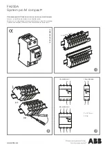
In (A)
t (s)
tr
lr
lg
li
lsd
tsd
tg
l²t
Configuration using adjustment dial, joystick and embedded display.
- Signalling the status of the trip unit via LED (Ready).
- Signalling the PTA overload pre-alarm via LED (adjustable threshold)
- Signalling the overload alarm via LED (>Ir).
- Possible adjustment of the thresholds and time delays of the LSIG protection.
- Possible adjustment of the neutral pole protection on 4-pole versions
(neutral positioned on the left).
Protection function
L - Long time delay protection
S - Short time delay protection
I - Instantaneous protection
G - Ground protection
Setting all the protection parameters. See § 3.2 Protection function.
Measurement function
See § 3.3 Measurement function
Alarm management
Pre-alarms
I - Instantaneous protection
Ii (ac15/-15%)
In = 40 A; 100 A: Ii (x In)
3 - 4 - 5 - 6 - 7 - 8 - 10 - 12 - 15
In = 160 A; 250 A: Ii (x In)
3 - 4 - 5 - 6 - 7 - 8 - 9 - 10 - 11
time delay (ms)
fixed
non-tripping time (ms)
10
maximum cut-off time (ms)
50
G - Ground protection
Ig (ac10/ -10%)
Ig = In x…
OFF - 40% for In = 40 A; 20% for In > 40 A
time delay (ms)
200 (fixed); I²t activated according to Isd I²t
non-tripping time (ms)
180
maximum cut-off time (ms)
250
Neutral adjustment (4P only)
neutral protection (Ir, Isd) x …
OFF - 50% - 100%
instantaneous neutral protection li Same as phases
time delay
Same as tr, tsd and instantaneous
Summary of Contents for h3+
Page 1: ...Moulded Case Circuit Breakers up to 250 A h3 Communication System manual...
Page 2: ...2 6LE005550A...
Page 4: ...4 6LE005550A...
Page 10: ......
Page 116: ...116 6LE005550A...
Page 124: ...124 6LE005550A...
Page 125: ...125 6LE005550A Support Page 6 1 Troubleshooting 126...
Page 127: ...127 6LE005550A...