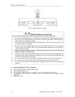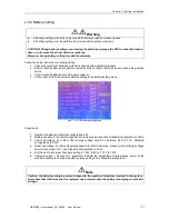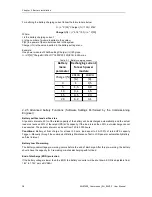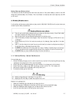
Chapter 1 Installation
20
MUST400_User manual_EN_REV02 User Manual
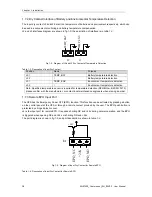
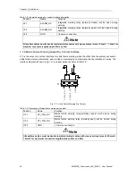
Table.1- 5: Description of Status Interface and Connection of Generator
Position
Name
Purpose
J5.1
+24V
In24V power supply
J5.2
GEN
Connection status of generator
J5.3
GND
Power ground
Note
All auxiliary cables must be double insulated twisted cables with cross sectional area of 0.5mm2
~ 1.5mm2 for maximum connection length between 25m and 50m.
1.7.5 BCB Input Port
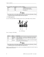
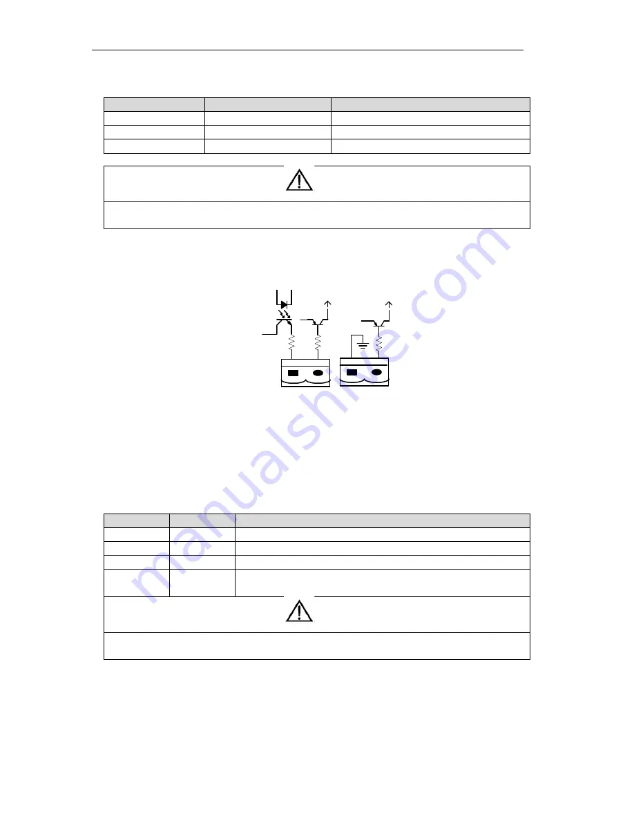
J6 and J7 are the ports of BCB. The diagram is shown in fig.1-8, and description is shown in table.1-6.
B
C
B
_
D
R
V
B
C
B
_
C
O
N
T
J6
J7
B
C
B
_
O
N
L
+24V
+24V
+24V
Fig.1- 8: BCB Interface
Table.1- 6: Description of BCB Interface
Note:
In case of BACKFEED protection option required, the system change the meaning of the contacts here above for
piloting backfeed protection device.
警告
危 险
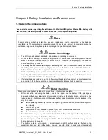
Position
Name
Description
J6.1
BCB_DRV
BCB actuating signal, provide the actuating signal of +24V, 20mA
J6.2
BCB_CONT
BCB contact status, connect with the normally open signal of BCB
J7.1
GND
Common connection
J7.2
BCB_ONL
BCB on-line
–
input (normally open) , BCB is on-line when the signal
is connecting with common connection
Note
All auxiliary cables must be double insulated twisted cables with cross sectional area of 0.5mm2
~ 1.5mm2 for maximum connection length between 25m and 50m.
警告
危 险

