Chapter 7 Operator Control and Display Panel
MUST400_User manual_EN_REV02 User Manual
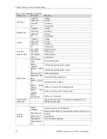
61
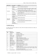
failure status and recover the mains power in time
26
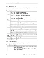
Batt Test OK
Battery Test OK
27
Batt Maint OK
Battery maintenance succeed
28
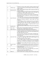
N#
Comm
Node
Join
The N# Power Module is inserted in system.
29
N# Comm Node Exit The N# Power Module is pulled out from system.
30
N# REC Fail
The N# Power Module Rectifier Fail, The rectifier has fault and results in
rectifier shutdown and battery discharging.
31
N# INV Fail
The N# Power Module Inverter Fail. The inverter output voltage is
abnormal and the load transfers to bypass.
32
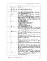
N# REC OV Temp.
The N# Power Module Rectifier Over Temperature. The temperature of
the rectifier IGBTs is too high to keep rectifier running. This alarm is
triggered by the signal from the temperature monitoring device mounted
in the rectifier IGBTs. The UPS recovers automatically after the over
temperature signal disappears.
If over temperature exists, check:
1. Whether the ambient temperature is too high.
2. Whether the ventilation channel is blocked.
3. Whether fan fault happens.
4. Whether the input voltage is too low.
33
N# Fan Fail
At least one fan fails in the N# power module.
34
N# Output Ov Load
The N# Power Module Output Over Load. This alarm appears when the
load rises above 100% of nominal rating. The alarm automatically resets
once the overload condition is removed.
1. Check which phase has overload through the load (%) displayed in
LCD so as to confirm if this alarm is true.
2. If this alarm is true, measure the actual output current to confirm if the
displayed value is correct.
Disconnect non-critical load. In parallel system, this alarm will be
triggered if the load is severely imbalanced.
35
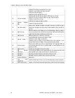
N# INV Ov Load
Tout
N# Power Module Inverter Over Load Timeout. The UPS overload status
continues and the overload times out.
Note:
The highest loaded phase will indicate overload timing-out first.
When the timer is active, then the alarm “unit over load” should also be
active as the load is above nominal.
When the time has expired, the inverter Switch is opened and the load
transferred to bypass.
If the load decreases to lower than 95%, after 2 minutes, the system will
transfer back to inverter mode. Check the load (%) displayed in LCD so
as to confirm if this alarm is true. If LCD displays that overload happens,
then check the actual load and confirm if the UPS has over load before
alarm happens.
36
N# INV Ov Temp.
The N# Power Module Inverter Over Temperature.
The temperature of the inverter heat sink is too high to keep inverter
running. This alarm is triggered by the signal from the temperature
monitoring device mounted in the inverter IGBTs. The UPS recovers
automatically after the over temperature signal disappears.
If over temperature exists, check:

