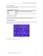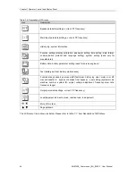
Chapter 7 Operator Control and Display Panel
MUST400_User manual_EN_REV02 User Manual
57
C
u
rr
e
n
t
V
o
lt
a
g
e
F
re
q
u
e
n
c
y
P
F
C
u
rr
e
n
t
V
o
lt
a
g
e
F
re
q
u
e
n
c
y
P
F
S
y
e
te
m
In
fo
rm
a
ti
o
n
P
a
s
s
w
o
rd
S
e
t
D
a
te
F
o
rm
a
ti
o
n
T
im
e
S
e
t
C
o
m
m
u
n
ic
a
ti
o
n
s
e
t
L
a
n
g
u
a
g
e
M
o
d
b
u
s
S
N
T
M
o
d
e
A
d
d
re
s
s
B
a
u
d
ra
te
P
a
ri
ty
B
a
tt
e
ry
v
o
lt
a
g
e
B
a
tt
e
ry
c
u
rr
e
n
t
B
a
tt
e
ry
s
ta
tu
s
E
n
v
ir
o
m
e
n
ta
l
te
m
p
e
ra
tu
re
B
a
tt
e
ry
t
e
m
p
e
ra
tu
re
R
e
m
a
in
e
d
c
a
p
a
c
it
y
R
e
m
a
in
e
d
t
im
e
B
a
tt
e
ry
s
e
t
N
u
m
b
e
r,
A
H
,f
lo
a
t
v
o
lt
a
g
e
,
b
o
o
s
t
v
o
lt
a
g
e
,E
O
D
v
o
lt
a
g
e
,c
h
a
rg
e
c
u
rr
e
n
t
B
a
tt
e
ry
s
e
lf
t
e
s
t
B
a
tt
e
ry
m
a
in
te
n
a
n
c
e
t
e
s
t
M
a
n
u
a
l
b
o
o
s
t
M
a
n
u
a
l
fl
o
a
t
S
to
p
t
e
s
t
C
a
b
in
e
t
a
d
ju
s
tm
e
n
t
O
u
tp
u
t
v
o
lt
a
g
e
a
d
ju
s
tm
e
n
t
B
y
p
a
s
s
v
o
lt
a
g
e
a
d
ju
s
tm
e
n
t
Current
Voltage
Frequency
PF
Apparent Power
Active Power
Reactive Power
Load percent
Faultclear
History log clear
Mute on/off
Manully transfer to bypass
Service set
Power module
1#~10#
S
-c
o
d
e
L
is
t
M
o
d
u
le
s
o
ft
w
a
re
v
e
rs
io
n
B
a
tt
e
ry
v
o
lt
a
g
e
B
a
tt
e
ry
c
u
rr
e
n
t
D
c
b
u
s
v
o
lt
a
g
e
RM200/20:cabinet
200kva/power module 20kva
N=03(P-1 / 2): N=03 modules in cabinet, parallel
mode, cabinet ID is 1, 2 cabinets are paralleled
Mute on/off
Current status
M1
M2
M3
M4
M5
M6
M7
M8
M9
M10
O/P data
O/P wave
L
C
D
s
e
t
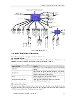
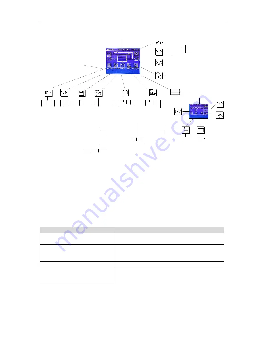
Fig.7- 3: Menu Tree Structure
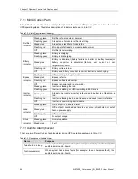
7.3 Detailed Description of Menu Items
The LCD main display shown in fig.7-3 is described in details below.
UPS information window
UPS information window: display the current time and UPS name. The information of the window is not
necessary for the user to operate. The information of this window is given in table.7-6.
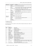
Table.7- 6: Description of Items in UPS System Information Window
Display contents
Meaning
MUST200
UPS system model. 200=200KVA cabinet, 120=120KVA
cabinet
N=03( P-1/2)
N=03 means the power modules inserted in the system.
P=parallel mode, 1/2=system number 1 and 2 system in
parallel. S=single mode. E=ECO mode.
12:00
Current Time (format: 24 hours, hour : minute)
(Status) Normal, alarm, fault
Normal: UPS in normal condition
Alarm: UPS has general alarm, such as AC input fault
Fault: UPS fuse or hardware fault
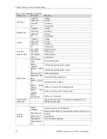
UPS menu and data window
UPS menu window displays the menu name of data window, while the data window displays the related
contents of selected menu in menu window. Select UPS menu and data window to browse related parameters
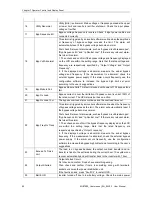
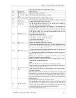
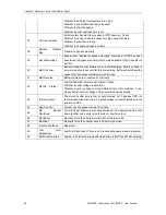
of UPS and set related functions. The details are given in table.7-7.

